Hardware Operation
Powering On the Robot
Before operation, please confirm again that you have read and ensured compliance with the Safety Guidelines content, eliminated potential risks, and ensured operational safety.
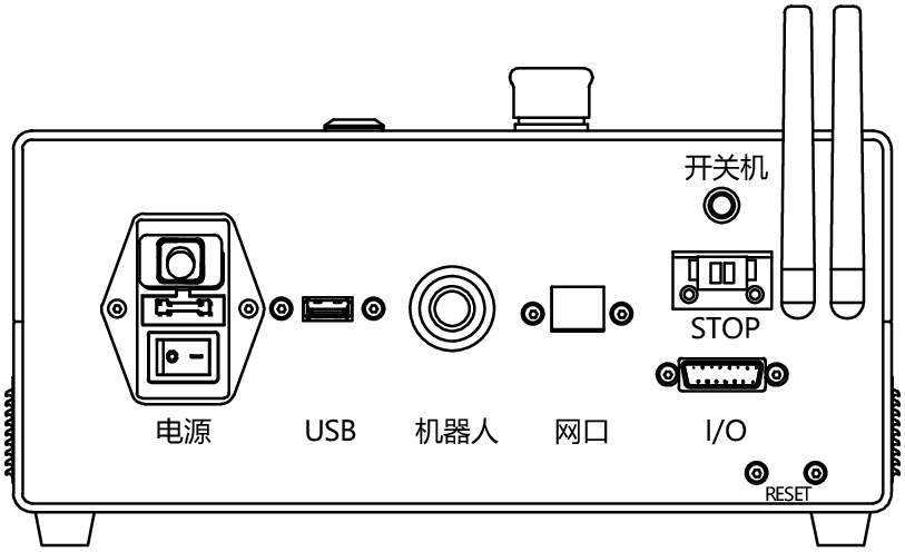
- Insert the robot cable plug into the robot interface of the control box.
- Plug the power cord into the control box and connect the power plug to a 220V AC socket.
- Ensure that the emergency stop button on top of the control box is in the released state (when the emergency stop button is in the raised state, it is released; when pressed, it is locked).
- Turn on the red main power switch on the back panel of the control box; the switch indicator light will illuminate.
- Long press (about 3 seconds) the power button on top of the control box or the external power button (optional) until the indicator light on the power button on top of the control box turns solid blue. Wait for the light on the robot's shoulder to turn on, completing the power-on operation for both the control box and the robot.
DANGER
- Please ensure that the power strip for the control box is properly grounded.
- Please ensure that the input current of the control box power supply is protected by a leakage protection device and an appropriate overcurrent circuit breaker.
- Please ensure that all cables are correctly connected before the control box is powered on, and always use the original power cord correctly.
Warning
- Do not disconnect or forcefully pull the robot cable when the robot is starting.
- Do not extend or modify the robot cable.
- Do not damage the power cord or place heavy objects on it.
- Do not use damaged or non-compliant sockets.
- Do not allow dust or metal attachments to adhere to the power plug and socket.
Connecting to the Robot
LM3 supports both wired network connection and wireless network connection. Currently, wireless network connection only supports connecting to the built-in Wi-Fi hotspot network of the control box.
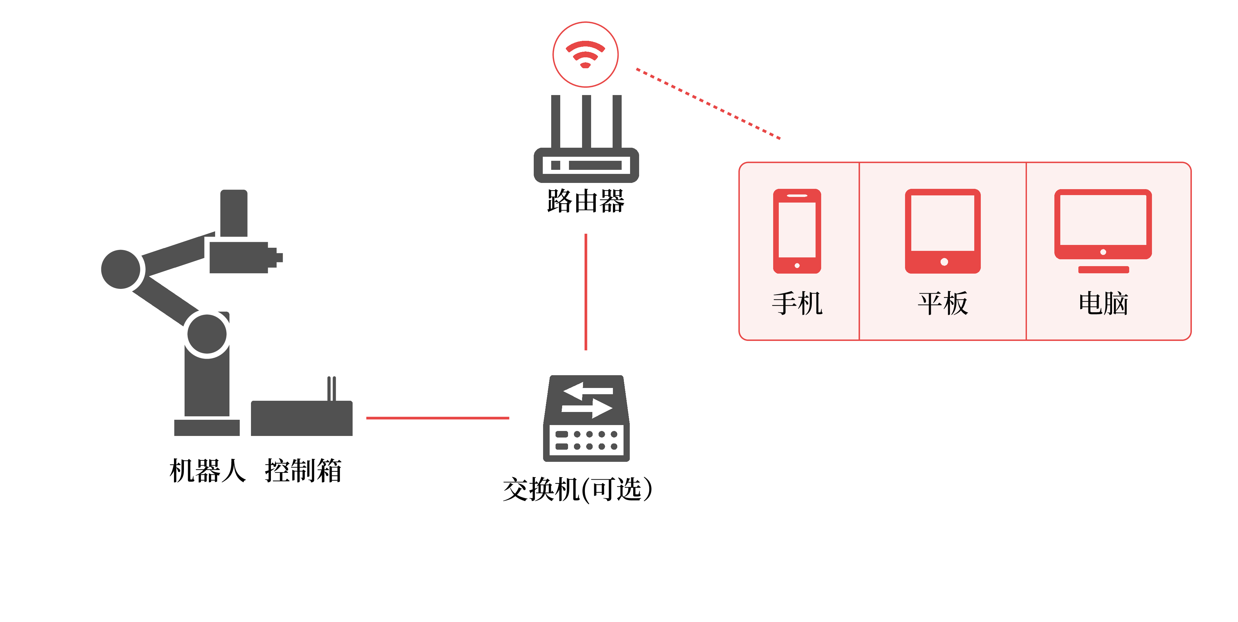
Wired Network Connection
As shown in the figure, use a standard network cable (Category 5 or above) to connect the Ethernet interface on the back panel of the control box to the LAN port of a router or switch. At the same time, ensure that the computer, tablet, phone, or other graphical terminal device used to operate the robot is connected to the same network as the robot.
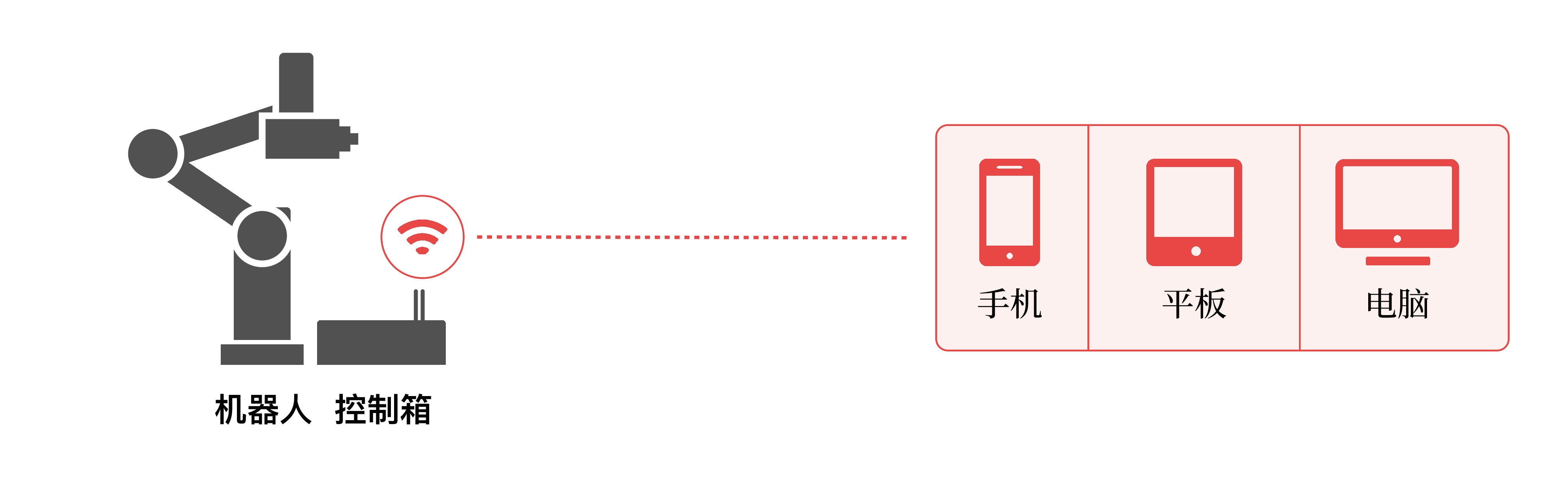
Wireless Network Connection
After the robot leaves the factory, it will by default enable a Wi-Fi hotspot with the device name as its SSID (you can find the device name on the nameplate of the control box). The device name format is like: Lebai-123456 (the last 6 digits are random characters), and the default password is: 88888888 (eight 8s). You can connect to this Wi-Fi hotspot network corresponding to the device name through the Wi-Fi function of your computer, tablet, phone, or other graphical terminal device to connect and control the robot.
Modifying the device nickname in the settings page will change the wireless SSID of the device.
Login
Familiarity with the operation of the L Master system will help you to more conveniently and quickly get started with using our company's robot products. Open the browser on your computer, tablet, phone, or other graphical terminal device and enter the following address in the address bar:
- If using a wired network, the address is:
http://IP. Search for "LeBai Robot" in the WeChat Mini Program, view the IP address corresponding to the device name through the "LeBai Robot Mini Program", or scan the QR code on the robot/control box to get the wired network address. - If using a wireless hotspot, the address is: http://10.20.17.1
After the webpage opens, you will enter the login page. Please enter the default authorization code: 1111 to log in to L Master. The login authorization code can be modified on the settings page.
Setup Wizard
When the robot is powered on for the first time after unboxing, you need to follow the prompts on the setup wizard page to complete the initial installation settings when logging into L Master for the first time.
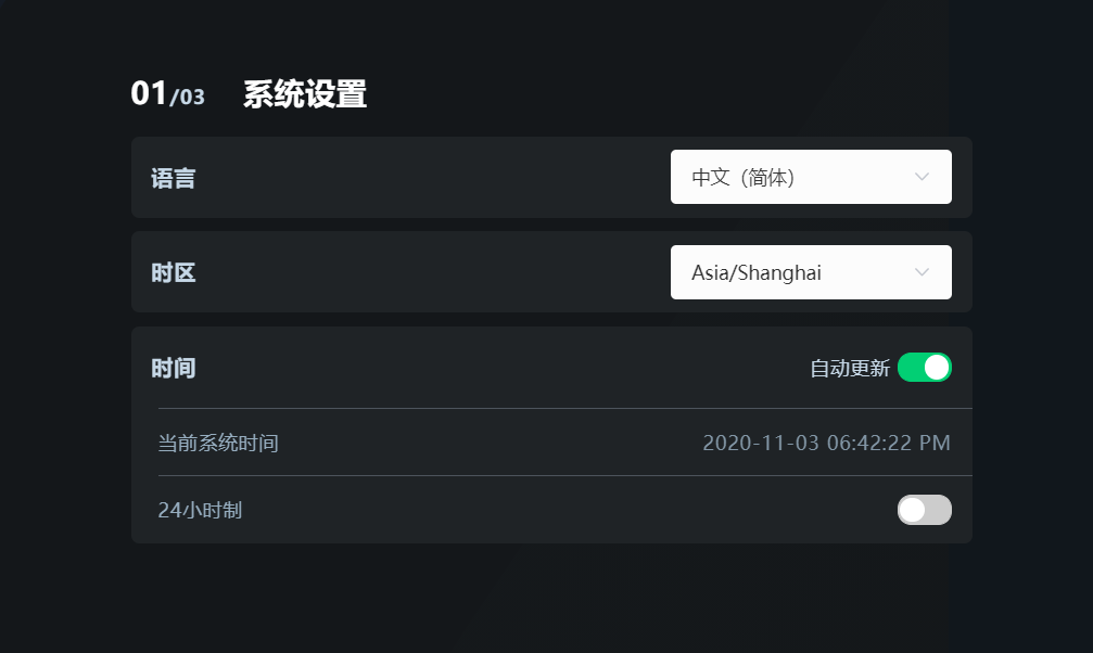
System Settings
In "System Settings", you can customize the language, time zone, and time.
Robot Settings
In "Robot Settings", you can set the robot's installation method, operation mode, and collision detection.
Installation Method
According to the actual installation method, refer to the "Icon Reference Table" in the image to select normal installation, inverted installation, or side installation.
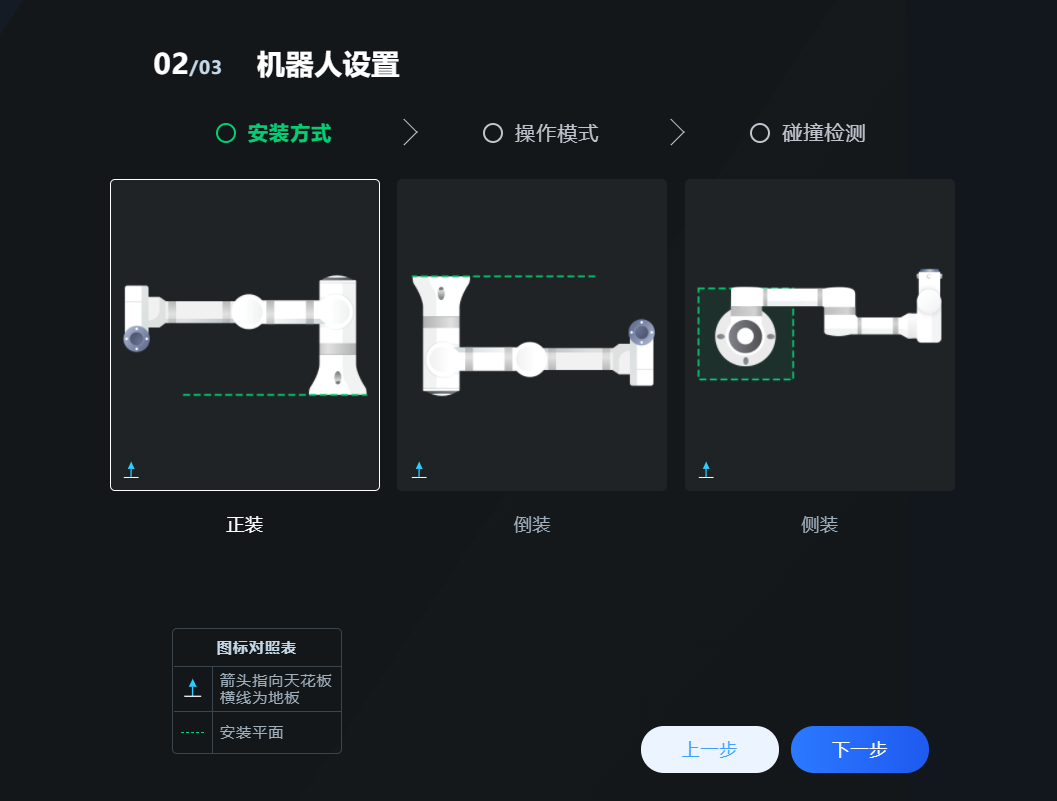
DANGER
The selection of the installation method must be consistent with the actual installation method, otherwise it may lead to accidental injury.
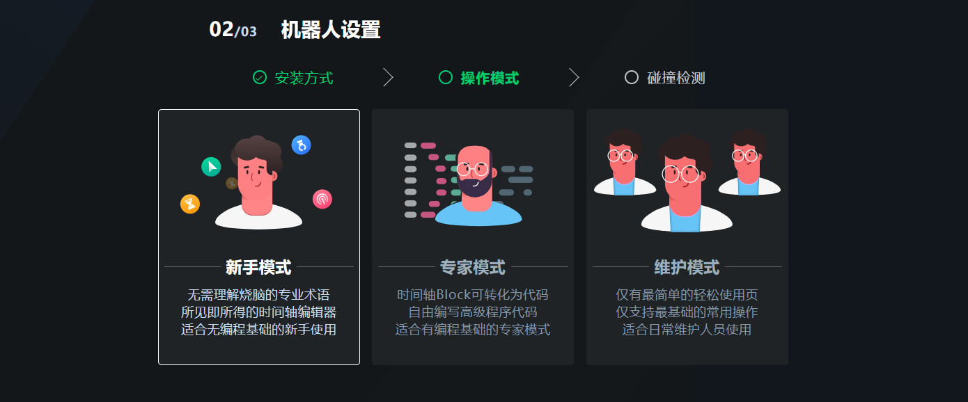
Operation Mode
You can choose between "Novice Mode", "Expert Mode", and "Maintenance Mode".
- Novice Mode is suitable for beginners without programming background, no need to understand any logic or code;
- Expert Mode is suitable for advanced users with some programming and logical foundation;
- Maintenance Mode is suitable for daily maintenance personnel, this mode only includes the most basic common operations. You can choose the appropriate operation mode according to your own situation.
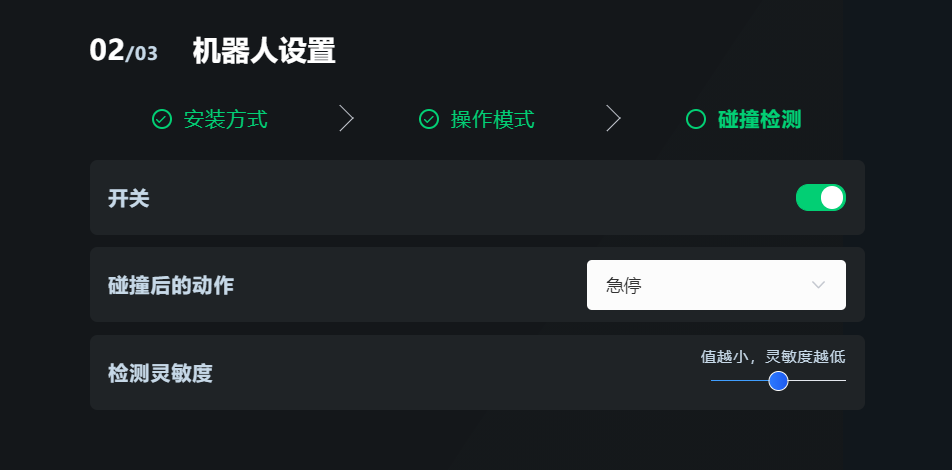
Collision Detection
The detection switch is on by default, the "Action after collision" is set to "Emergency Stop" by default, you can choose between "Emergency Stop" or "Pause", and you can drag the slider to adjust the "Detection Sensitivity". Click [Next] to enter the interface settings.
DANGER
During the operation of the robot, whether the "Collision Detection" function is enabled or not, it is forbidden to enter the robot's workspace without protection, otherwise there is a risk of personnel being hit by the robot. See Workspace for details.
Interface Settings
Set the interface theme in "Interface Settings", it is recommended to use the "Dark Theme".
Click [Finish] to enter the L Master homepage.
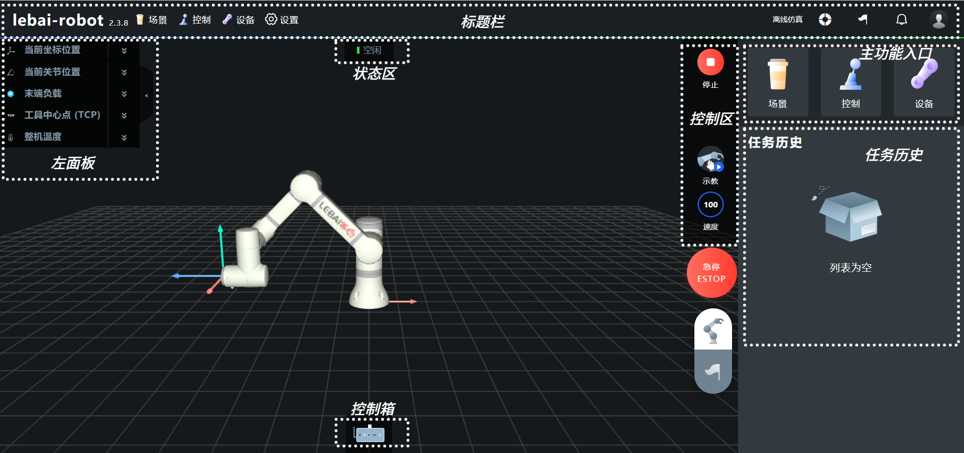
Homepage
On the L Master homepage, the page is divided into seven areas: left panel, status area, control area, main function entrance, task history, bottom control box, and top title bar. The emergency stop button and capsule control area can be adjusted by long-pressing and dragging.
- The left panel displays the robot's current coordinate position and pose data, joint space angle data, end load mass and center of mass, tool center point (TCP) position and pose data, and overall temperature data. Individual and all menu items in the left panel can be expanded/hidden.
- The status area displays the real-time status of the robot.
- The control area includes the robot's start/stop buttons, software teaching button, speed ratio adjustment control, and hidden task pause/resume button.
- The main function entrance includes three main function entrances: scene, control, and device.
- The task history includes a list of all task histories.
- The bottom control box, when expanded, includes power on/off button, wireless network IP, wired network IP, communication protocol, and voltage and current information.
- The top title bar displays the robot name and version number, scene, control, device, and system settings on the left side; the right side includes switching between real machine online and offline simulation, function entrances for ordering and easy use, task history, message center, and logout.
- The upper half of the capsule control area is for status control, and the lower half is for task history.
Robot Status
| Status Code | Status | Description |
|---|---|---|
| -1 | ERROR | Robot software control system abnormal |
| 0 | DISCONNECTED | Robot hardware communication failure |
| 1 | ESTOP | Robot is in emergency stop state, please confirm safety |
| 2 | BOOTING | Robot is initializing |
| 3 | ROBOT_OFF | Robot power is not turned on |
| 4 | ROBOT_ON | Robot power is turned on |
| 5 | IDLE | Robot is in idle state |
| 6 | PAUSED | Robot is in paused state |
| 7 | MOVING | Robot is moving |
| 8 | UPDATING | Robot system is updating |
| 9 | STARTING | Robot is in the startup process from initialization complete to idle |
| 10 | STOPPING | Robot is transitioning from idle state to stop state |
| 11 | TEACHING | Robot is in teaching mode |
| 12 | STOP | Robot is in stop state, not emergency stop state |
Position Information
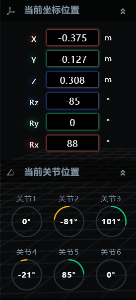
The left panel of the L Master homepage synchronizes the robot's position information in real-time, including coordinate space and joint space. As shown in the figure, the current coordinate position displays real-time data of the robot's position and pose in coordinate space; the current joint position displays real-time data of the robot's 6 joint angles.
Temperature Information
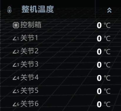
As shown in the figure, the left panel of the L Master homepage displays the real-time temperature of the robot's control box and each joint. The normal temperature of each joint is between room temperature and 65°C.
Warning
When the joint temperature display exceeds 65°C, do not touch the robot's surface, otherwise there is a risk of high-temperature burns. Please shut down immediately, wait for the machine temperature to return to normal, then check whether the current robot load exceeds the rated effective load of 3 kg or whether the robot has collided with external objects.
Speed Ratio
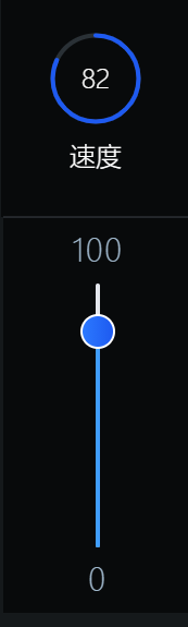
Click the speed icon in the control area of the L Master homepage, drag the slider or click on the slider bar in the expanded slider as shown in the figure to adjust the robot's operating speed ratio. The ratio range is 0~100.
Message Center
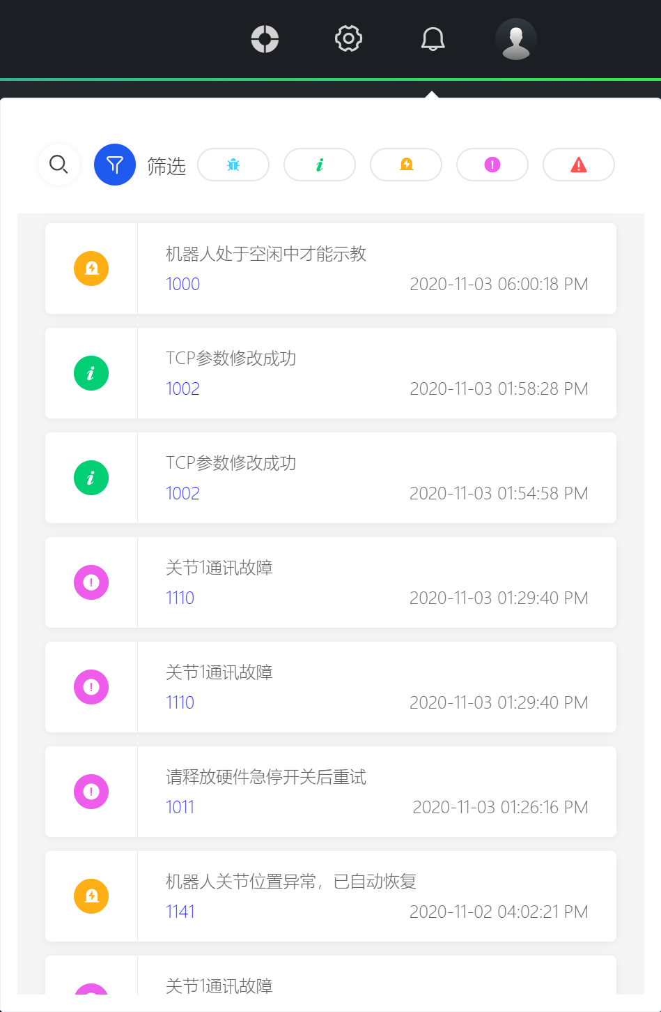
In the message center, you can view message notifications for robot prompts, warnings, and software and hardware abnormalities. Click the message icon in the upper right corner of the L Master homepage to open the message center.
In the message center, there are two ways to search for messages:
- Search for message notifications by keywords.
- Filter message notifications by the following types:
- Information Information reminder messages;
- Warning System runtime warning level reminders, generally do not affect usage;
- Error The system has encountered an error, need to keep attention to the occurrence probability of the error, if it occurs frequently, need to click to view the solution as soon as possible or contact our company in time;
- Fatal The system has encountered a serious error, there is a risk of operation or it can no longer operate normally. In this case, you must stop immediately, view the solution, or contact our company in time.
As shown in the figure, The number in the lower left corner of a single message is the error code. Click the error code link to jump to the corresponding error code solution page on our company's official website. On this page, you can find the problem explanation and solution corresponding to the error code.
Task History
On the L Master homepage, or by clicking the small flag button in the title bar, you can view the task history.
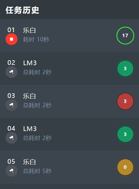
The task history list shows the tasks that are currently running and completed, including the name of each task, time spent, number of runs, and status, displayed in chronological order.
- When a task is running, the task abort button is displayed on the left, and the running status on the right is displayed in blue;
- When a task is completed, the rerun button (flag icon) is displayed on the left, click to rerun the currently selected task. The status bar on the right is green indicating the task is completed; yellow indicates the task has been aborted; red indicates the task has been emergency stopped.
Click on the task name in "Task History" to enter the scene editing page corresponding to that task.
Warning
When running a scene, the task of that scene enters the task history list. After the task is completed, clicking the [Rerun] button will execute the task with the scene data from the previous execution of that task. The rerun task is not affected by changes to the scene data and is based on the scene data from the last run of the task.
Offline Simulation
Click the button in the title bar to switch the system between offline simulation mode and real machine online mode. The software system will restart during the switching process.
- "Real Machine Online" mode is to directly operate the robot to execute tasks through the software system.
- "Offline Simulation" is offline operation, using the simulated robot model in the system interface for simulated operation.
Starting the Robot
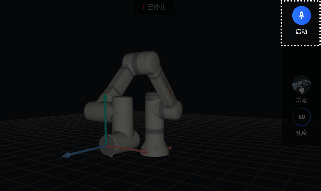
Enter L Master, as shown in the figure, click the start button in the control area; after a brief "Starting", the status area on the homepage turns to "Idle", indicating that you have successfully started the robot.
Stopping the Robot
When the robot is in "Running" or "Idle" status, you can click the red stop button on the homepage or in the capsule control area as shown in the figure; after a brief "Stopping", when the robot status changes to "Stopped", it indicates that you have successfully stopped the robot.
Emergency Stopping the Robot
- Software Emergency Stop The red [Emergency Stop] (ESTOP) button in the lower right corner of L Master;
- Hardware Emergency Stop Press the emergency stop button (red protruding button) on top of the control box or the external emergency stop button (optional).
WARNING
After using the hardware emergency stop operation, the emergency stop operation will not be automatically released. You need to rotate the emergency stop button clockwise to unlock and complete the release.
Shutting Down the Robot
- First stop or emergency stop the robot.
- There are two ways to shut down, you can choose either:
- Software shutdown: Select the control box icon at the bottom of the L Master homepage, click to flip open and then click the leftmost shutdown button.
- Hardware shutdown: Long press the power button on the control box or use the external power button (optional) until the blue indicator light on the control box power button goes out.
- Turn off the red main power switch on the back panel of the control box.
Warning
Shutting down the robot must strictly follow the above operation steps, otherwise it may cause problems such as damage to the robot file system, robot function failure, etc.