Software Operation
This chapter describes how to use L Master version 2.x.
Drag Teaching
Before discussing how to create and write a scene, let's first understand the scene editor of the LEBAI robot and how to perform drag teaching operations.
Drag Teaching: This allows the robot to be guided by hand, and when the end tool's mass and center of mass are correctly set, the robot can achieve a self-balancing operating state.
- In L Master, click the teaching icon to enable teaching mode, drag the robot to the specified position, and click the teaching icon again to exit teaching mode.
- Long press the protruding button at the end of the robot (see Hardware Buttons) to enable teaching mode, drag the robot to the specified position, and release the button to exit teaching mode.
Warning
Before using drag teaching, make sure to correctly set up the end device (see Operating Safety).
Warning
During teaching, be careful not to exceed the safe range of joint angles (see Operating Safety), as this may cause the robot to emergency stop or other malfunctions.
Scene Editor
You can program the robot in the scene editor, i.e., write scenes.
Timeline Editor
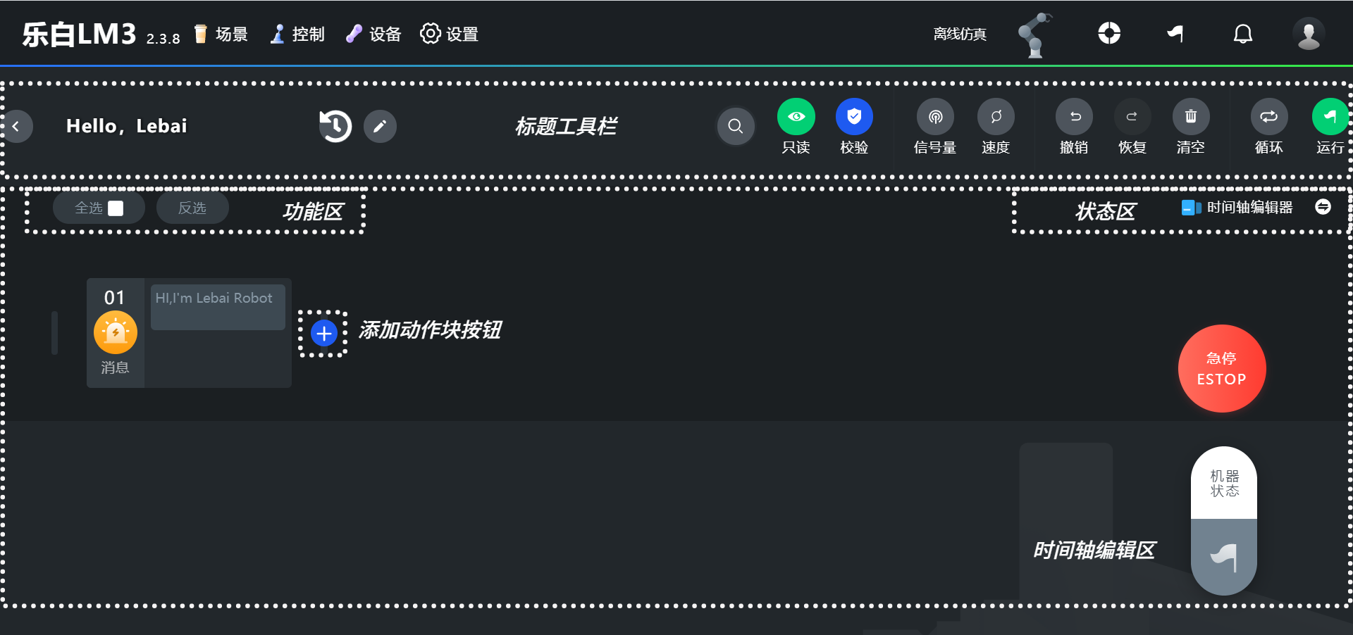
A visual, low-threshold scene editor that doesn't require understanding any logical relationships. Suitable for beginners, you only need to add corresponding action blocks in the timeline editor as needed to make the robot move.
In the scene's timeline editor, each independent operable element is called an action block (Block), and a collection of several action blocks can be packaged into an action package.
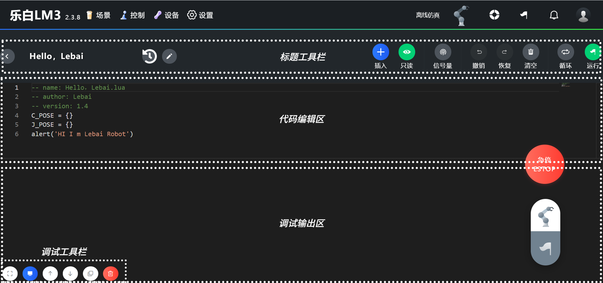
Code Editor
A scene editor based on the Lua language that supports complex logical operations. Suitable for users with a certain programming foundation and logical thinking, you can make the robot move by writing corresponding code (as shown in the figure).
Switching Editor Types
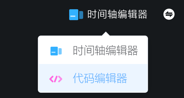
The code editor is only available in expert mode. The steps to switch from the timeline editor to the code editor are as follows:
- Enter "Settings", click "Operation Mode", or click the switch button to the right of "Timeline Editor" in the status area to enter the operation mode selection page, select "Expert Mode", and click the [Save] button in the upper right corner of the operation mode page.
- Return to the previously edited scene.
- In the timeline editor, move the mouse to the "Timeline Editor" button, and select "Code Editor" from the pop-up menu to switch.
Once a scene's editor type is switched from timeline editor to code editor, it cannot be converted back. Before performing this operation, use the "Export" (see Export Scene) or "Copy" function to backup.
Writing Scenes
Creating a New Scene
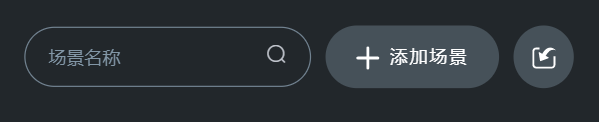
Click the "Scenes" button on the L Master homepage to enter the "Scene List", click the [Add Scene] button on the right side of the toolbar on this page, enter the scene name to complete the creation of a new scene.
Position Action Block
Click the add action block button in the timeline editor to pop up the dialog box as shown in the figure.
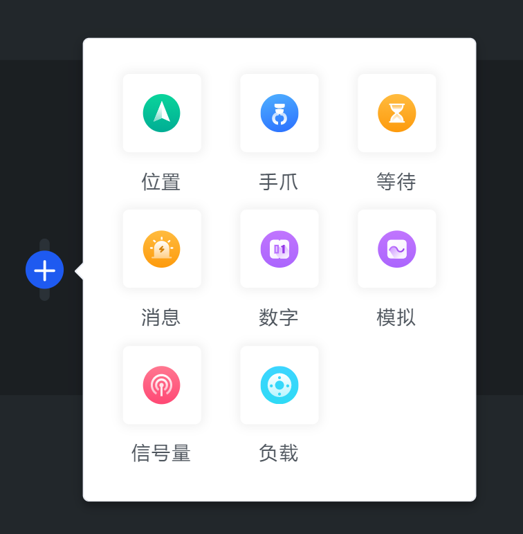
As the core control module in robot control, position control in the timeline editor only requires adding position action blocks according to the following tutorial to make the robot perform corresponding types of trajectory movements according to predetermined position actions.
The position mentioned in this manual is an abbreviation for the robot's position and posture data. When position and posture are not specifically mentioned later in this document, position refers to both the robot's position and posture.
Adding Positions
There are two methods to add positions in the timeline editor, you can choose either:
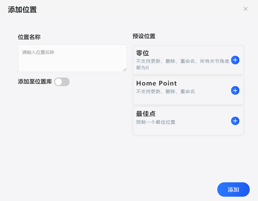
- Click the add action block button in the editing area of the timeline editor, select "Position", enter the position name in the opened add position dialog box, click the [Add] button to save the current position of the robot in a new position action block.
An action block is the smallest visual editing module in the timeline editor, with one module representing one type of action. Action types include: Position, I/O, etc.
- Double-click the protruding button at the end of the robot, and the system will save the current position of the robot in a new position action block.
By combining drag teaching and the above method of adding position action blocks, add the desired position action blocks (can be any number) according to your needs until the scene writing is complete.
Editing Positions
As shown in the figure, place the cursor on the position block to bring the current position block into focus.
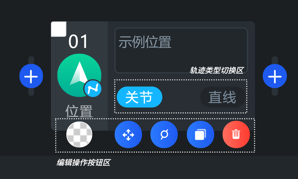
The two buttons in the trajectory type switching area are used to switch between joint space movement (movej) and Cartesian space linear movement (movel).
- Icon represents movement in joint space, which is the robot's motion space described by the angle of each joint of the robot.
- Icon represents linear movement in Cartesian space, which is the rectangular coordinate system space we commonly use.
The buttons in the editing operation button area from left to right are:
- Style: Can change the background color of the action block. The color of the style button is consistent with the background color of the action block, and when the action block is selected, it will highlight the action block with this color as the background. Specially, the default style is transparent, and the highlight background color of the action block after selection is blue. Style, copy, and delete buttons are common buttons in the action block operation area.
- Fine-tuning: Fine-tune and update the position data stored in the current position block.
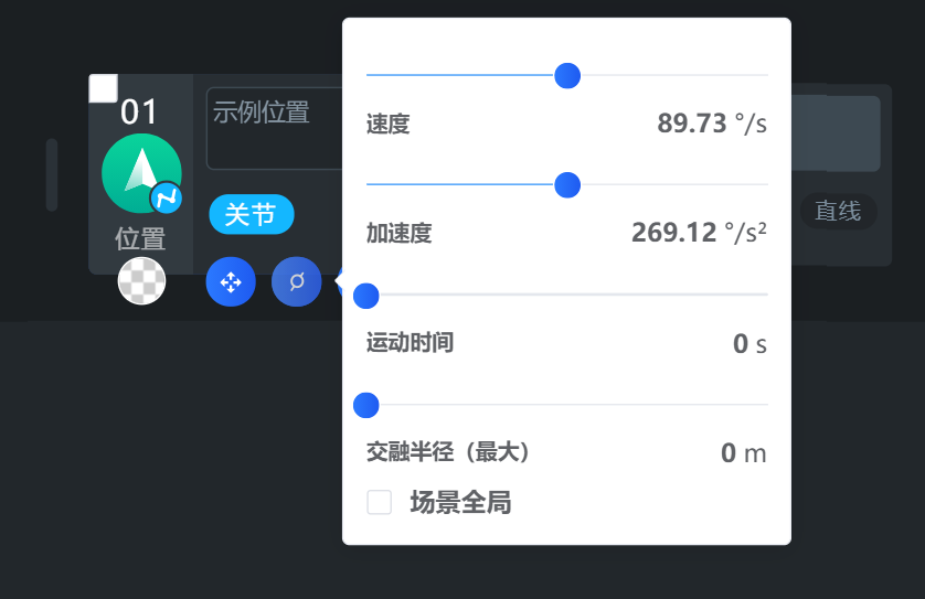
- Motion parameters: Adjust the speed and acceleration of the position block, or time, as well as the blending radius (smoothing option).
- Copy: Copy the current action block.
- Delete: Can delete the current action block.
Fine-tuning
When editing a scene, if you need to precisely adjust the position in the motion trajectory, you can fine-tune individual positions. Select the fine-tuning icon, and the page will automatically jump to the fine-tuning page.
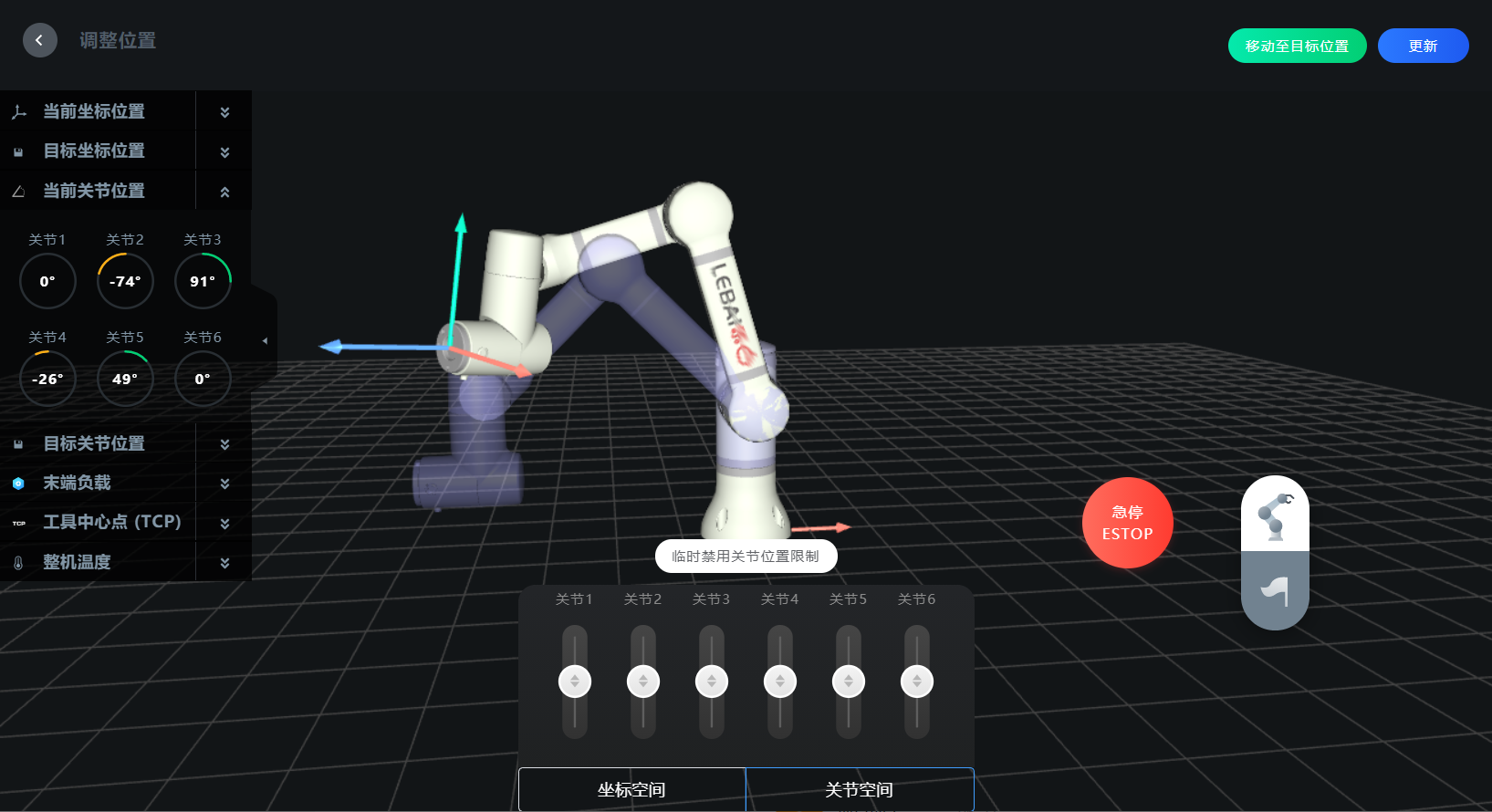
The function area on the left panel of the fine-tuning page can be expanded to view the current coordinate position data and target coordinate position data of the robot. When the robot's current position is inconsistent with the target position stored in the position block, a virtual robot and a real robot will appear on the fine-tuning page, where the virtual robot represents the target position stored in the current position block, and the real robot represents the actual current position of the robot.
Coordinate Space Fine-tuning
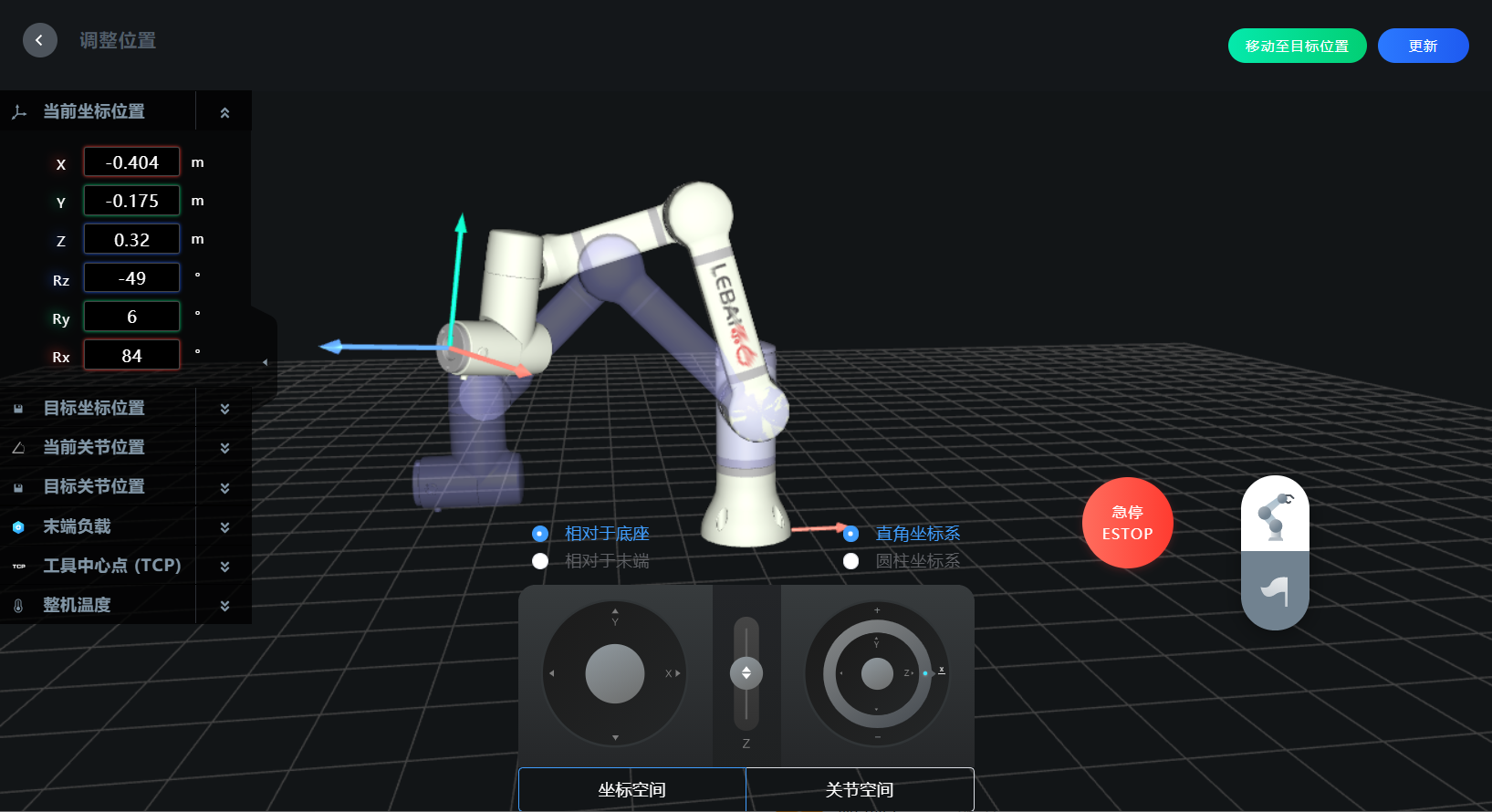 When fine-tuning, you can choose different reference coordinate systems and coordinate system representations:
- Relative to the base, you can use a rectangular coordinate system or cylindrical coordinate system.
- Relative to the end, only rectangular coordinate system is supported.
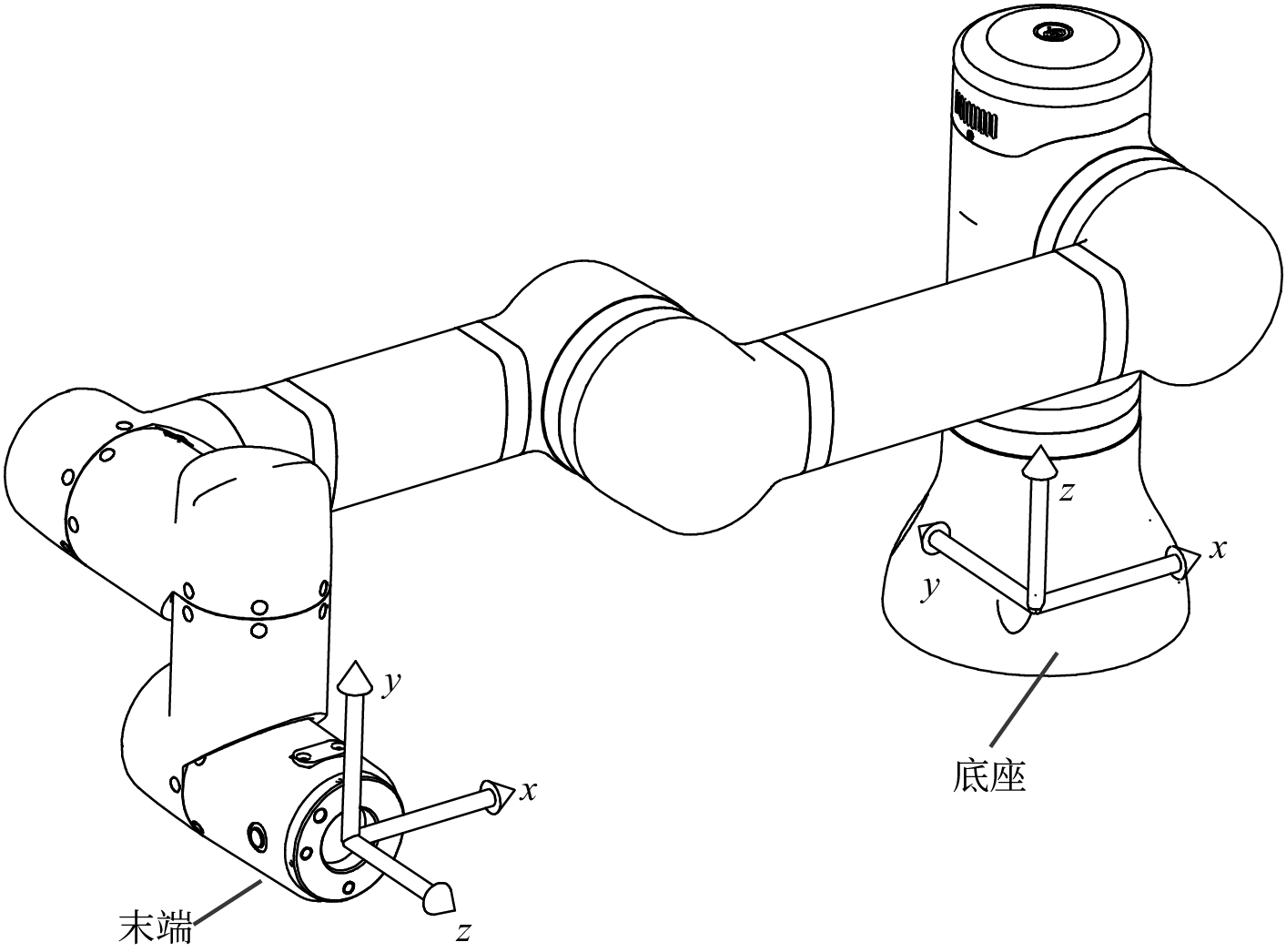
When the reference coordinate system is selected as "relative to the base", it means that the center of the robot's base plane is used as the origin of the world coordinate system.
By selecting the rectangular coordinate system as the adjustment method, enter the values of position or posture in the position information display box on the fine-tuning page, and the robot will automatically move to the position you need; or by pulling the sliders at the bottom of the screen in various directions, when the slider is released, the fine-tuning stops. Click the [Update] button to complete the position fine-tuning.
The LEBAI robot uses the EulerZYX representation method for posture representation in Cartesian space (rectangular coordinate system space). For details on the EulerZYX representation method, see Position and Posture. The posture can also be described as .
The LEBAI robot uses the Euler angles (EulerZYX) to describe the posture of the robot's end, that is, first rotate angle around the axis of the coordinate system, then rotate angle around the axis of the rotated coordinate system, and finally rotate angle around the axis of the coordinate system rotated twice.
When the reference coordinate system is selected as "relative to the end" (without adding TCP, see TCP Settings), it uses the center of the robot's flange plate plane as the origin of the coordinate system. Using the rectangular coordinate system as the adjustment method, enter the values of position/posture in the current coordinate position box on the fine-tuning page, or pull the sliders at the bottom of the screen to operate. After the robot automatically moves to the specified position, click [Update] to complete the position fine-tuning.
Joint Space Fine-tuning
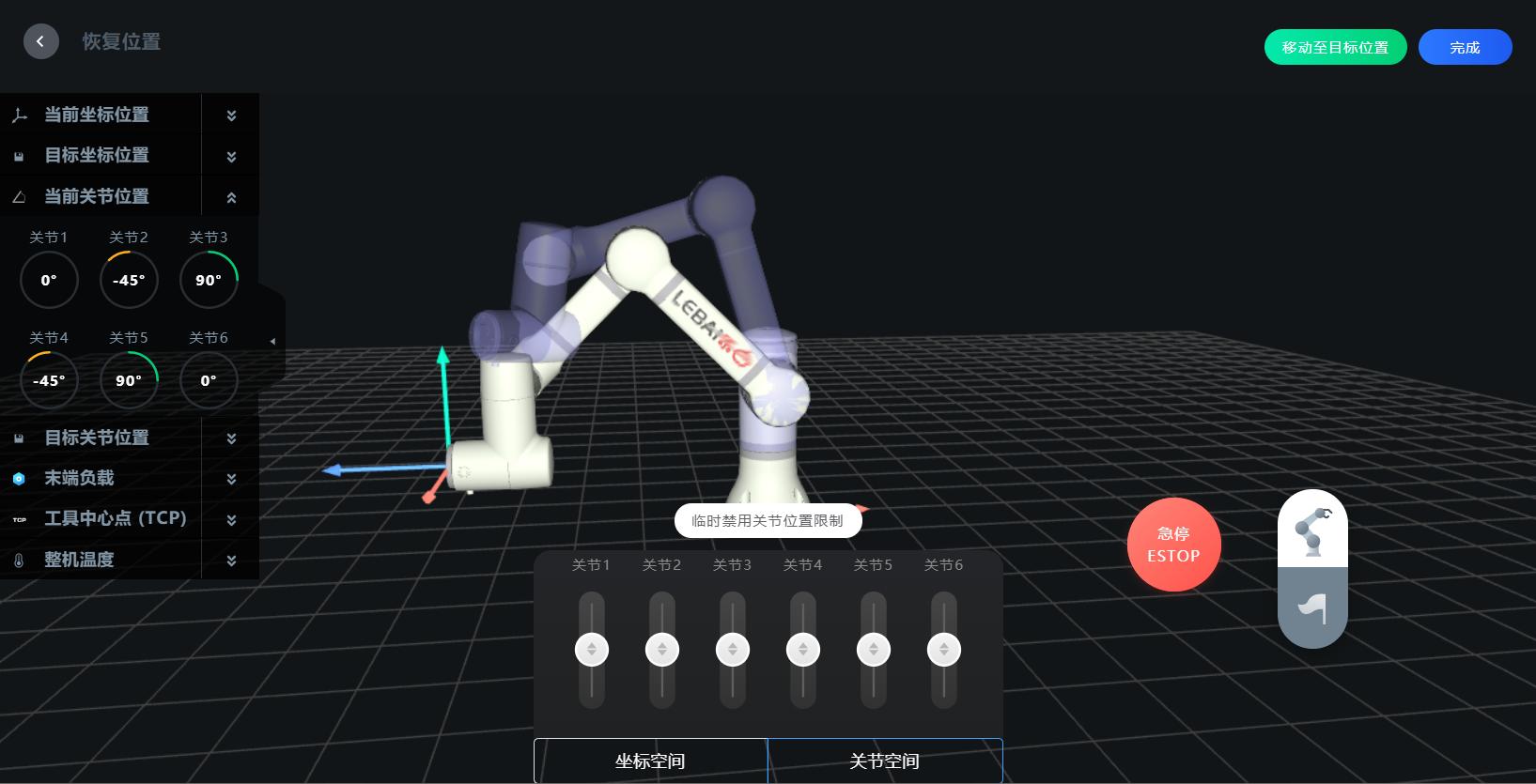
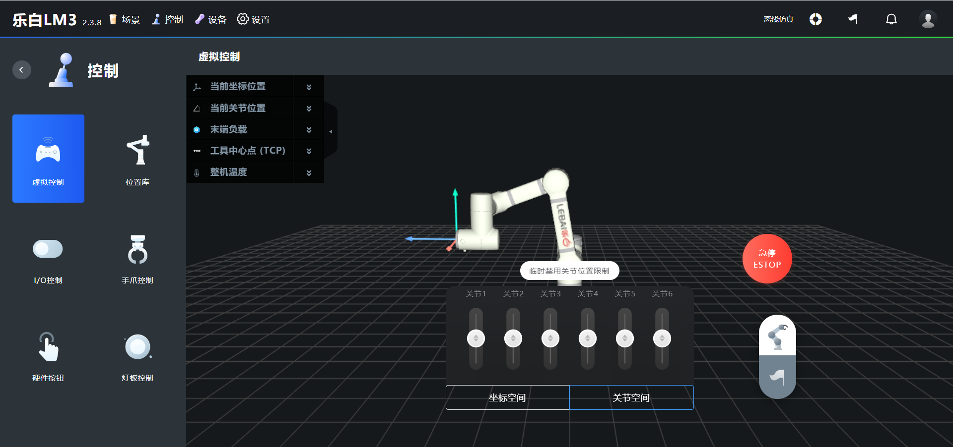
Click "Joint Space" at the bottom of the fine-tuning page to switch to joint space fine-tuning. In the left panel function area of the fine-tuning page, you can expand to view the robot's current joint position data and target joint position data. By entering the angle values for joints 1 to 6, the robot will automatically reach the specified position; or by pulling the sliders at the bottom of the screen in various directions, when the slider is released, the fine-tuning stops. Click [Update] to complete the position fine-tuning.
WARNING
When the robot stops due to joint limit during operation, the user can click [Temporarily Disable Joint Position Limit] in the joint space fine-tuning after restarting to release the joint restriction (20s) for position fine-tuning operation.
Speed Controls
Speed controls can modify the running speed , acceleration , time , and blending radius of the scene or position action block. Users can operate globally on the toolbar of the scene editor, or click the button of a single position block for individual operation.
The speed of a single position block is set to use the scene global function by default, which means it is consistent with the current scene's global settings. Uncheck the function checkbox before "Scene Global" to adjust the speed parameters for a single position block.
The speed of a single position block can be operated by adjusting the speed and acceleration or by modifying the movement time.
Blending Radius
When the blending radius is set to be greater than 0, the robot action instruction trajectory will not stop at the specified target position, but will move continuously in a smooth way, making the action continuity better, moving time shorter, and efficiency higher.
When the blending radius is set to 0, the robot trajectory can accurately reach the target position coordinates of each position block.
After adding position action blocks, if you don't need to add other types of action blocks, you can directly refer to the content of Running Scenes.
Gripper Action Block
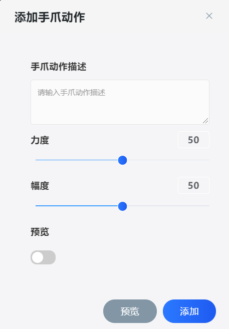
Select "Gripper" in the add action block pop-up box to open the add gripper action dialog. Enter the gripper action description, set the force and amplitude. If you need to preview the opening and closing effect of the gripper, turn on the "Preview" switch (real-time preview) or click the [Preview] button (manual preview). After confirming that the effect is correct, click [Add].
Wait Action Block
Select "Wait" in the add action block pop-up box and enter the number of seconds to wait.
Message Prompt Action Block
Select "Message Prompt" in the add action block pop-up box. Message prompts are divided into light panel prompts and pop-up prompts. The light panel prompt can choose from multiple styles:
- Off Turn off the light panel display;
- Constant Keep the light panel constantly lit in the specified color;
- Breathing The light panel breathes according to the specified color;
- Equal Division Rotation The light panel rotates and displays according to 2 or 4 different specified colors evenly distributed;
- Same Color Rotation The light panel rotates and displays according to a certain color;
- Flashing The light panel flashes according to a certain color.
Digital I/O Action Block
Select "Digital I/O" in the add action block pop-up box. In the pop-up add dialog, the top tab corresponds to the operation type of digital I/O. The digital I/O action block supports three types of operations:
- Read Read the input value of a certain digital I/O port;
- Wait When executing to this action block, it will wait for a certain digital I/O value to be the selected value, and will stay at this action block until it changes to the selected value;
- Set Set the output value of a certain digital I/O port.
There are three types of digital I/O ports: control box I/O, flange I/O, and external I/O (if any).
Click [Add] to complete the insertion of the digital I/O action block.
WARNING
Please confirm that the I/O input and output electrical connections to be used are normal before running the task.
WARNING
Please confirm that the digital I/O input and output electrical connections are normal before running the task.
Analog I/O Action Block
Select "Analog I/O" in the add action block pop-up box. In the pop-up add dialog, the top tab corresponds to the operation type of analog I/O. The analog I/O action block supports three types of operations:
- Read Read the input value of a certain analog I/O port;
- Wait When executing to this action block, it will wait for the judgment condition of a certain analog I/O value and the selected value to be true, and will stay at this action block until the condition is true;
- Set Set the output value of a certain analog I/O port.
There are only two types of analog I/O ports: control box I/O and external I/O (if any). The flange currently has no analog I/O ports.
Click [Add] to complete the insertion of the analog I/O action block.
WARNING
Please confirm that the analog I/O input and output electrical connections are normal before running the task.
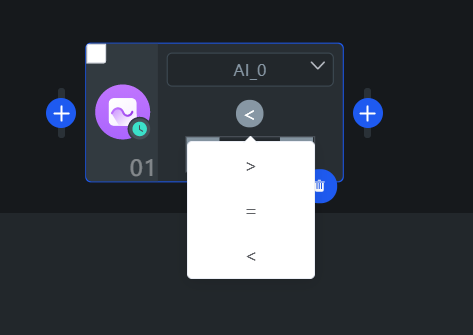
Among them, under the wait operation type, there are three judgment conditions: >, =, <. When clicking the wait condition button of a certain wait analog I/O position block (as shown in the figure), the corresponding judgment condition can be modified.
Load Configuration Action Block
Select "Load Configuration" in the add action block pop-up box, enter the load mass or center of mass that needs to be modified in the add load configuration dialog box. This function is used to dynamically modify the mass and center of mass of the load during program execution.
Warning
When the robot end is installed with an end tool, and the tool has the function of picking up/placing items, it is necessary to insert an action block corresponding to the change of the end load mass and center of mass after picking up/placing in the corresponding position of the timeline editor. If not set properly, it may reduce the life of the corresponding parts of the robot, and may cause false alarms in collision detection.
Warning
When adding load configuration, the settings of mass and center of mass must be as consistent as possible with the mass of the end tool. When changing or removing the end tool, be sure to modify the load parameters accordingly or disable the corresponding end device, otherwise it may cause accidental injury.
Toolbar
- When entering an empty scene, the toolbar of the timeline editor is in edit mode, providing search, edit, operate, and execute functions for the scene.
- When entering a scene with added action blocks, the toolbar of the timeline editor is in read-only mode, providing view, loop, and run functions.
Users can switch between toolbar modes by clicking the read-only and edit buttons.

Scene Time Machine
The scene time machine saves the data information modified by users in the scene in real-time. When users make modifications during scene editing, the system will automatically save the modified data information and name it with the scene name and storage time.
Click the clock icon after the toolbar title text to enter the scene time machine. Click on a storage data in the time machine list to enter the corresponding scene.
Modify Scene Name
Click the modify button after the toolbar title text to modify the scene name in the pop-up scene modification dialog box.
Search
Click the search button to expand the action block search box.

When the search box is expanded, click the icon on the left side of the search box to quickly search based on the action block types in the pop-up box. At the same time, you can also combine the keywords entered in the text input box to query action blocks that match the keyword under the corresponding type or all types.
Speed Controls
The speed controls on the toolbar are the configuration entry for the current scene's global speed controls.
When not using the speed control adjustment operation for individual position action blocks mentioned in Edit Position, all position action blocks under this scene use the global speed control configuration.
Undo/Redo
When you accidentally delete an action block or perform an incorrect operation, you can click the undo button to perform the undo operation; conversely, if you want to restore a previously undone operation, you can click the redo button to perform the restore operation.
Warning
When returning or exiting from the current editor page, the editor's undo and redo history will be cleared, and when returning to the current scene editor again, you will not be able to perform the previous undo and restore operations.
Delete/Clear
When some action blocks are selected in the editing area, the delete/clear button will display the number of corresponding selected action blocks. Clicking this button at this time will execute the operation of deleting the corresponding action blocks; when no action blocks are selected in the editing area, clicking this button will execute the operation of clearing the current scene.
Warning
Please make sure you are aware of the consequences of performing this operation and execute this operation when you confirm the deletion or clearing for the second time, especially when you have exited the current editor after performing the delete or clear operation, you will not be able to restore the state before deletion or clearing when you enter the scene editing operation again.
Scene Loop Count
Click the loop count icon in the upper right corner of the timeline editor toolbar to modify the task loop count (default loop is 1 time); when the count is 0, it means executing an infinite loop task until the robot emergency stops or stops.
Running Scenes
There are two methods to run a scene, you can choose either:
- Click the run task icon in the upper right corner of the toolbar.
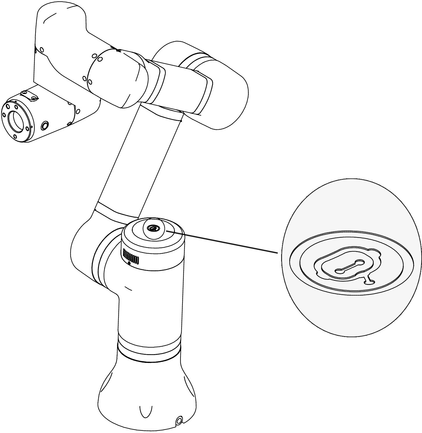
- Double-click the shoulder button of the robot, as shown in the figure (the button with a "white" mark in the middle of the shoulder light panel).
Robot Position Safety Check
When the current position of the robot is consistent with the first position to be run in the scene, the scene runs without performing a position safety check; when the current position of the robot is inconsistent with the first position to be run in the scene, a position safety check will be performed before running the scene and a position safety check page will pop up.
First position to be run: In the timeline editor, the first position-type action block found in order among the qualified action blocks (if no action blocks are selected, it means all action blocks in the editor, or if some action blocks are manually selected, it means these selected action blocks) is the first position to be run. The robot control system will check and compare based on the position of this action block and the current position of the robot.
On the position safety check page, you can use the following two operations to move the robot to the first position to be run in the scene:
- Click [Move to Target Position] on the position safety check page, wait for the robot to run to the first position to be run in the scene. You can click [Stop] at any time during the running process to stop the movement.
- Long press the end flat button of the robot, the robot will move to the first position to be run in the task, release the end flat button after reaching the position.
Click the [Complete] button in the upper right corner, and the scene will start running. During the scene running, long press the shoulder button to pause or resume the task.
TIP
When the operation mode is novice mode, the robot position safety check always remains on and cannot be modified. When in expert mode and using the timeline editor, users can choose to turn on/off the robot position safety check function.
Warning
After using the end flat button to move to the first position to be run, please keep a safe distance from the robot and click the [Complete] button to run the scene, otherwise it may cause accidental injury.
Batch editing of action blocks, the action block type and subtype (if the type of action block has a subtype) must be consistent.
Import and Export
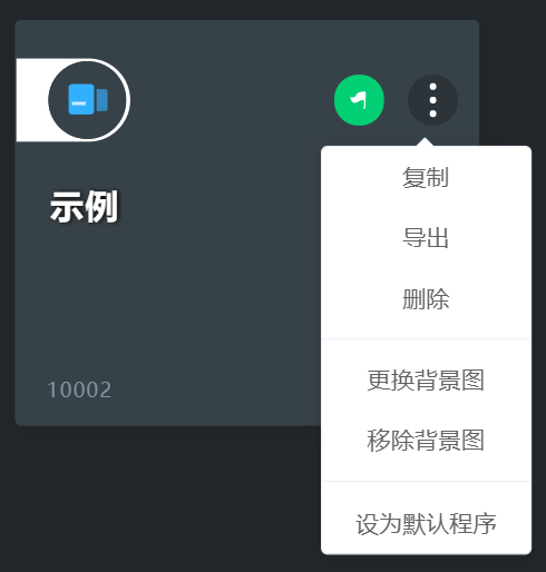
Scenes can be exported. On the scene list page, select the scene you need to save, move the mouse to the button in the upper right corner of the scene card, pop up the scene menu, select "Export", and choose the save location of the scene file in the pop-up save dialog box (the scene file name is *.lbd).
Scenes can be imported. As shown in the figure, click import scene in the toolbar of the "Scene List", open the previously exported scene file, and after the import is completed, it will automatically enter the scene.
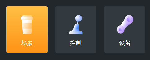
Control
Virtual Control
Through virtual control, you can adjust the current position and posture of the robot.
For specific operation methods, refer to the fine-tuning function introduction in Fine-tuning.
Hardware Buttons
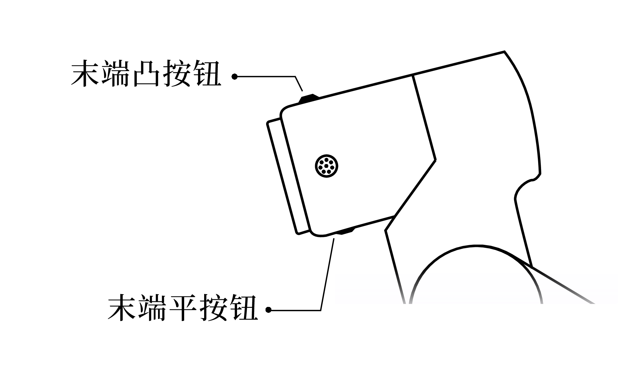
- End Flat Button
- Single Click Move the timeline editing focus one action block forward;
- Double Click Move the timeline editing focus one action block backward;
- Long Press If currently in the position action block refresh position pop-up (enter by clicking the fine-tuning button of the position block) or the position library apply position pop-up, move to the corresponding target position;
- Release When long pressing to enter the move to target position operation, releasing will stop the current movement.
- End Protruding Button
- Long Press Enter teaching mode;
- Release Exit teaching mode;
- Double Click Add a position action block/code in the editor;
- Single Click Under the premise that the current action block is a position action block, if the current position action block has not entered the fine-tuning position dialog, clicking this button will enter the fine-tuning current position dialog; if it has already entered the fine-tuning position dialog, clicking this button means updating the position data saved by the current action block.
- Shoulder Button
- Long Press Switch queue pause/resume operation, i.e., pause when "running", resume when "paused";
- Single Click Equivalent to clicking cancel operation (button, dialog box, etc.) when there is a pop-up in the scene editor or other interfaces;
- Double Click When currently in the scene editor interface and there are no other pop-ups, switch run/stop operation; when there is a pop-up in the scene editor or other interfaces, equivalent to clicking confirm operation (button, dialog box, etc.).
- Button Combination Operation
- Start/Stop Robot: Long press the end flat button and simultaneously long press the shoulder button to switch between starting and stopping the robot operation.
WARNING
The button combination operation for starting/stopping the robot is only valid when the current robot is not in emergency stop or power off.
Devices
Robot
In the case of wired connection, users can view the list of robots in the same local area network through "Robot", including device nickname, device name, device IP, and robot status information. Click on the specified robot IP to quickly open a new tab in the browser, which is the system login page of that robot.
End Devices
If you need to add end tools (such as grippers) to the robot end, click "Devices", click [Add] in the end device, set the mass and center of mass of the corresponding auxiliary tool, and click "Enable". If you need to remove the end tool, click "Disable".
Warning
- When adding end devices, the mass and center of mass settings of the end device must be as consistent as possible with the mass and center of mass of the end tool.
- When changing or removing the end tool, be sure to modify the mass and center of mass of the end device accordingly or turn off the corresponding end device, otherwise it may cause accidental injury.
TCP Settings
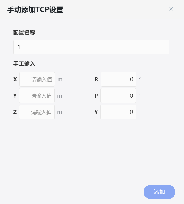
TCP stands for Tool Center Point. The TCP settings page is used to set the offset/transformation of the robot end TCP position and posture. By default, TCP is not set. When the robot is loaded with end tools, TCP settings can be selectively added according to the application needs of the scene.
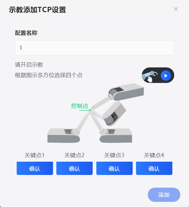
TCP can be added through teaching. Click the "Add by Teaching" option in the [Add] button menu to open the dialog for adding TCP settings by teaching. At this time, you can click the teaching icon and drag-teach the robot, making the robot end tool contact the same control point (i.e., keeping the end tool always in contact with the same position) while confirming four key points with four different postures. The robot can automatically identify the TCP position information based on different positions and directions of the end flange. Posture information needs to be filled in manually and does not support teaching addition.
Users can also enter the edit TCP settings dialog through "Manual Add" or [Edit] to manually set the position and posture of the end tool.
Settings
System Settings
Users can modify user display-related settings in system settings.
- Device Nickname Users can set an easy-to-remember name for the robot, which will be displayed in the upper left corner of the page and will also be used as the SSID of the Wi-Fi hotspot. The nickname is set to empty by default, and the SSID will be named after the device name on the device nameplate.
- Login Password Click to modify the password, users can modify the login password and login prompt of the current device. The password is a 4-digit number, and the initial password is
1111. The login prompt will be displayed when the user fails to log in. - Language Users can choose the display language of the software interface. Currently, except for "Chinese (Simplified)", all are machine translations, and changing the language does not affect the voice language of the speaker.
- Time Zone Modifying this setting will affect the running time of subsequent task history. The default is East Eight Zone (Asia/Shanghai).
- Time Enabling the automatic update option will turn on the system time synchronization service.
- Units Users can modify the display units of length, angle, temperature, weight, current, and torque on the software interface, and can also modify the number of decimal places for each unit. The system internally stores all in SI units, modifying this does not affect the data read and write method in Lua code.
Safety Settings
Collision Detection
The robot collision detection is set to "Emergency Stop" by default after being turned on in the installation guide page. The actions after the robot detects an external force collision during task execution are divided into two types: "Pause" and "Emergency Stop", and users can adjust the detection sensitivity themselves.
Actions after collision:
- Emergency Stop The robot needs to be restarted and taught to a safe position before continuing operation.
- Pause If a custom number of seconds is selected, the task will automatically resume running when the specified pause time is reached; if permanent pause is selected, you need to click the resume task button in the task history list bar on the homepage.
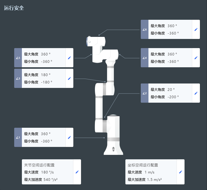
Operating Safety
In operating safety, you can view and adjust the following parameters during runtime:
- Maximum and minimum angles for each joint
- Joint space running configuration
- Coordinate space running configuration
WARNING
The minimum and maximum angles of joints can theoretically be set to any value. It is recommended to use the default values preset at the factory (shown in the above figure).
WARNING
Modifying the joint space running configuration will affect the robot's speed limit. When the speed of any joint during operation exceeds the maximum speed limit, the robot will automatically emergency stop.
DANGER
Modifying the joint space running configuration and modifying the coordinate space running configuration will proportionally affect the speed and acceleration time (acceleration) of position action blocks in the scene editor.
WARNING
Non-professional users should not arbitrarily change these settings if they are unsure of the risks after modification.
System Update
After entering the "System Update" page in "Settings", if the current system is already the latest version, no update is needed. Click [Check System], and the circular pattern in the center of the screen will show "Checking for updates".
When a system version update is detected, it will prompt "System update found and latest version number", click [Update] below, and the system will automatically update to the latest version.
WARNING
- Please make sure the robot status is "Stopped" before proceeding with the system update.
- During the system update, no other operations can be performed, otherwise it may lead to serious consequences such as damage to the robot system.
Backup and Restore
Click backup in "Backup and Restore" to backup all data information in the current scenes, controls, devices, and settings, named and compressed in the form of robot name + version + time.zip. The backup package can be downloaded and saved locally.
Users can select the backup information that needs to be restored in the backup file list, click the restore button in the upper right corner to complete the backup restoration; You can also upload or drag the downloaded backup data file to the page file upload area, click the restore button to complete the backup restoration.
The exported data can be used to copy device configuration information to another device.
Operation Mode
The operation mode can be switched through the following operations.
- Switch and save in "Operation Mode" on the "Settings" page.
- Switch and save using the switch icon in the upper right corner of the scene editing.
Novice Mode
Novice mode uses a low-threshold timeline editor. In novice mode, some functions of expert mode will be hidden to reduce the confusion caused by complex and advanced functions.
Expert Mode
In expert mode:
- It supports switching the editor type to code editor (programming language is Lua).
- Supports converting timeline editor version scenes to Lua code.
- Supports turning off position safety check in timeline editor mode.
- Supports installation settings that can be customized for any installation method configuration.
WARNING
Please make sure you fully understand the danger of this operation before turning off the position safety check.
Maintenance Mode
Maintenance mode only provides five basic functions: start/stop button, teaching button, emergency stop button, task panel, and message center, which facilitates daily operations for maintenance personnel.