Product Information
Unpacking
Open the packaging box and remove the robot body, control box, power cable, accessory package, and other products.
Product Composition
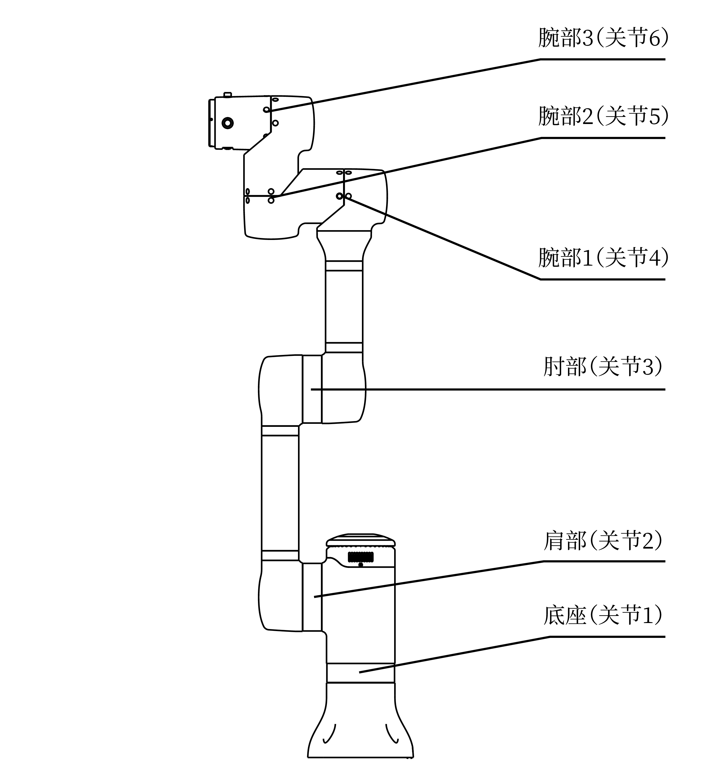
The LM3 series robot product mainly consists of the robot body and control box. The robot body has 6 rotating joints, i.e., 6 degrees of freedom (DoF). As shown in the figure, the robot joints include the base (Joint 1), shoulder (Joint 2), elbow (Joint 3), wrist 1 (Joint 4), wrist 2 (Joint 5), and wrist 3 (Joint 6).
The robot body (hereinafter referred to as the robot) is the executing mechanism of the robot product. The base is where the robot is installed, the shoulder and elbow can perform large-amplitude movements, wrist 1 and wrist 2 can perform more precise movements, and wrist 3 can connect to end tools.
The control box is the control part of the robot system, which can control the position and pose of the robot in the workspace and connect the electrical inputs and outputs of the device. In practical applications, to ensure operational safety, it is usually necessary to connect an external emergency stop switch (optional) to the control box. For convenience, an external power button (optional) can also be connected.
As shown in the figure below, the control box is connected to the robot via the robot cable. After connection and power-on (see Basic Operations), users can access the robot's L Master[1] system to control the robot and view various status information through a browser[2] on a computer, tablet, phone, or other graphical terminal device.

Basic Parameters
Robot Basic Parameters
| Degrees of Freedom | 6 | Working Radius | 638 mm |
| Effective Payload | ≤ 3 kg | Weight | 9.5 kg |
| Repeatability | ± 0.5 mm | End Speed | ≤ 2 m/s |
| Environmental Humidity | 25~85% (non-condensing) | Environmental Temperature | 0~40°C |
| Protection Rating | IP54 | Power Supply | 48 V (DC) |
| Installation Method | Normal, Inverted, Side | Installation Area | About 160 cm2 |
Control Box Basic Parameters
| Dimensions | 270×250×130(H) mm | Weight | 3.8 kg |
| Power Supply | 100~240 V (AC), 50~60 Hz | Cable Length | 2 m |
| Protection Rating | IP20 | Communication Protocol | Ethernet |
The typical power consumption of the control box and the entire robot is 130 W.
Control Box Electrical Specifications
| Parameter | Minimum | Typical | Maximum | Unit |
|---|---|---|---|---|
| Input Voltage | 100 | 220 | 240 | V (AC) |
| External Mains Fuse (100~240 V) | 18 | 20 | 22 | A |
| Input Frequency | 47 | 50 | 63 | Hz |
| Rated Working Power | 90 | 130 | 400 | W |
Motion Axes
The joint motion range of the LM3 robot is unrestricted, as shown in the table below.
| Joint | Motion Range | Maximum Speed |
|---|---|---|
| Joint 1 | Unrestricted | 180 °/s |
| Joint 2 | Unrestricted | 180 °/s |
| Joint 3 | Unrestricted | 180 °/s |
| Joint 4 | Unrestricted | 180 °/s |
| Joint 5 | Unrestricted | 180 °/s |
| Joint 6 | Unrestricted | 180 °/s |
The unrestricted joint motion range mentioned above excludes situations of robot self-interference, which may vary depending on the actual motion scenario.
Workspace
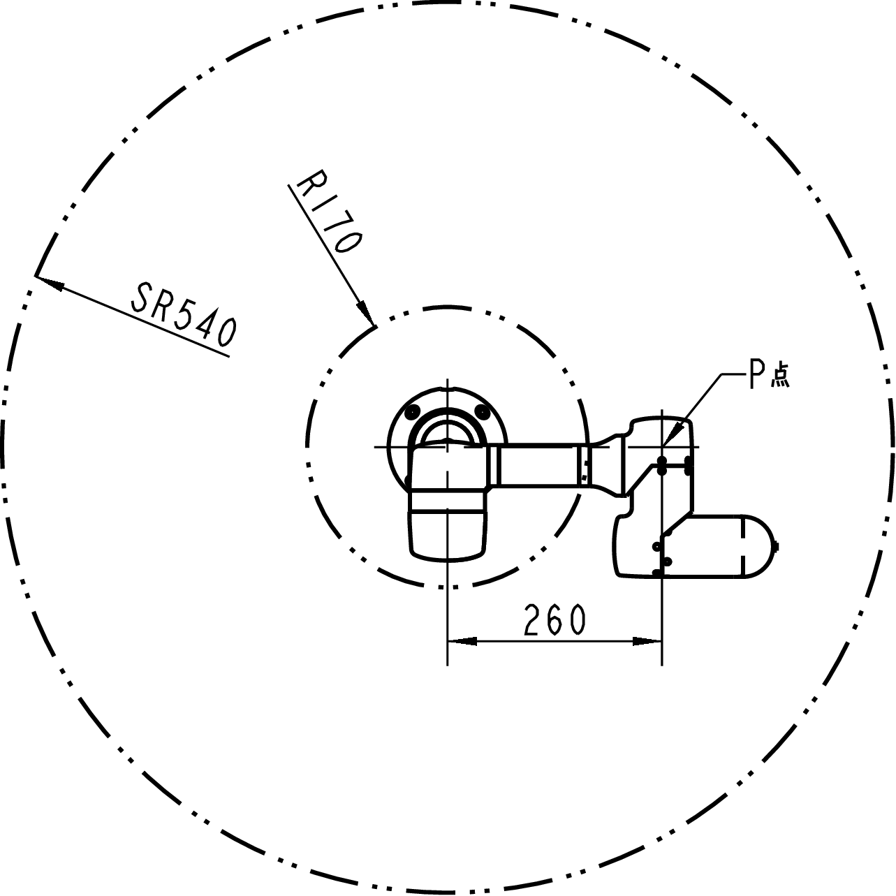
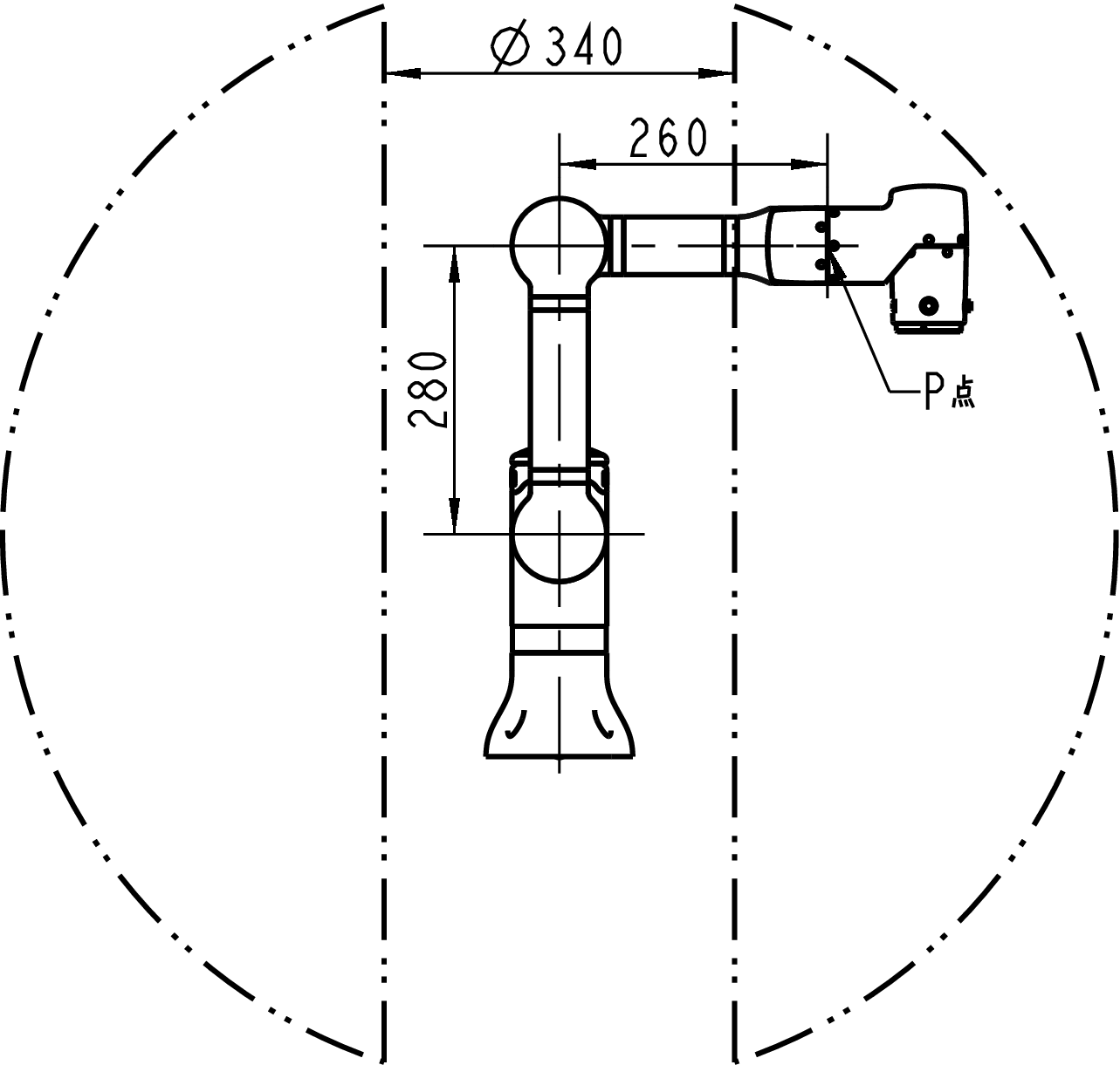
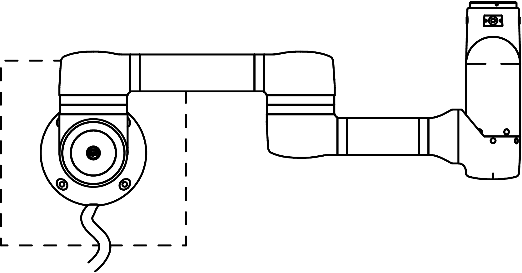
The workspace of the LM3 robot refers to the area within a 540 mm range around the base joint.
As shown in the LeBai robot workspace diagram above, the area indicated by the double-dot-dash line is the optimal operating area for point P.
I/O Interfaces
LM3 provides various I/O interfaces. Depending on different application scenarios, you can choose different I/O interfaces to implement corresponding I/O operations.
Control Box I/O
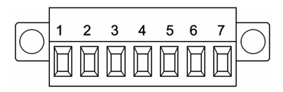
As shown in the diagram below, the robot control box provides physical I/O interfaces accessed through a DB15 male connector:
- 4 digital inputs, 4 digital outputs.
- 2 analog inputs, 2 analog outputs.
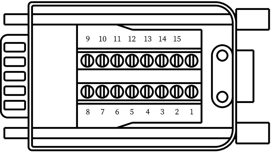
| Number | Interface | Port Property | Programming Example |
|---|---|---|---|
| 1 | Power Positive | 24 V | |
| 2 | Analog Output 1 | AO 0 | set_ao(0, val) |
| 3 | Analog Output 2 | AO 1 | set_ao(1, val) |
| 4 | Digital Output 1 | DO 0 | set_do(0, val) |
| 5 | Digital Output 2 | DO 1 | set_do(1, val) |
| 6 | Digital Output 3 | DO 2 | set_do(2, val) |
| 7 | Digital Output 4 | DO 3 | set_do(3, val) |
| 8 | Power Negative | - | |
| 9 | Analog Input 1 | AI 0 | get_ai(0) |
| 10 | Analog Input 2 | AI 1 | get_ai(1) |
| 11 | Digital Input 1 | DI 0 | get_di(0) |
| 12 | Digital Input 2 | DI 1 | get_di(1) |
| 13 | Digital Input 3 | DI 2 | get_di(2) |
| 14 | Digital Input 4 | DI 3 | get_di(3) |
| 15 | Power Negative | - |
- Digital inputs are PNP type, input voltage 3~30 V.
- Digital outputs are PNP type, output voltage 24 V, maximum total output current for 4 ports is 2 A.
- Analog inputs/outputs support the following two types:
- Voltage type: Input/output voltage 0~10 V.
- Current type: Input/output current 4~20 mA.
Flange I/O
As shown in the diagram below, I/O interfaces are provided on the end flange plate through SA810 access:
- 2 digital input interfaces.
- 2 digital output interfaces.

| Number | Interface | Port Property | Programming Example |
|---|---|---|---|
| 1 | Power Positive | 24 V | Maximum supply current 2 A |
| 2 | Power Negative | ||
| 3 | Digital Output 1 | FDO 0 | set_flange_do(0, val) |
| 4 | Digital Output 2 | FDO 1 | set_flange_do(1, val) |
| 5 | EIA-485 A | RS485 D- | |
| 6 | EIA-485 B | RS485 D+ | |
| 7 | Digital Input 1 | FDI 0 | get_flange_do(0) |
| 8 | Digital Input 2 | FDI 1 | get_flange_do(1) |
- Digital inputs are PNP type, input voltage 3~30 V.
- Digital outputs are PNP type, output voltage 24 V, maximum total output current for 2 ports is 1.5 A.
Voltage or current type analog inputs/outputs are not supported. Modbus/RTU protocol is supported on the RS485 interface.
TIP
In the LM6J trial production model, interfaces corresponding to numbers 5 and 6 are CANH and CANL respectively.
The new LMG-90 gripper only supports communication via RS485 serial protocol on the LM3 model and is not compatible with the CAN protocol.
Extended I/O
If the provided input and output interfaces are not enough, you can contact us for extended I/O modifications before purchasing the equipment.
The extended I/O board provides 12 pairs of digital inputs/outputs and 2 pairs of analog inputs/outputs.
Communication interface
The control box also provides communication interfaces for different protocols:
| Number | Function | Performance Parameters | Programming Example |
|---|---|---|---|
| 1 | RS485 | 485 interface A | serial. open ("/dev/ttyS1") |
| 2 | RS485 | 485 interface B | serial. open ("/dev/ttyS1") |
| 3 | TX-232 | 232 interface send | serial. open ("/dev/ttyS3") |
| 4 | RX-232 | 232 interface receiving | serial. open ("/dev/ttyS3") |
| 5 | TX-TTL | TTL signal transmission | serial. open ("/dev/ttyS2") |
| 6 | RX-TTL | TTL signal reception | serial. open ("/dev/ttyS2") |
| 7 | Signal Ground |
Network Connection
LM3 provides three network connection methods: Ethernet, Wi-Fi (2.4 GHz) hotspot network, and 4G cellular network. The control box is equipped with an RJ45 Ethernet interface (8P8C), a pair of Wi-Fi antennas, and a 4G antenna respectively.
The device connects to the cloud through the Internet of Things, and by default, only registers the device's online status. When you encounter difficulties in device debugging and need our remote assistance, we will seek your consent to connect to your device through the IoT platform, view device information, and possibly modify your device configuration.
TIP
Batches produced before 2020 do not have a pre-installed 4G IoT module and cannot help you solve problems through remote connection. If you need further support, you can contact our after-sales service for a discounted replacement.
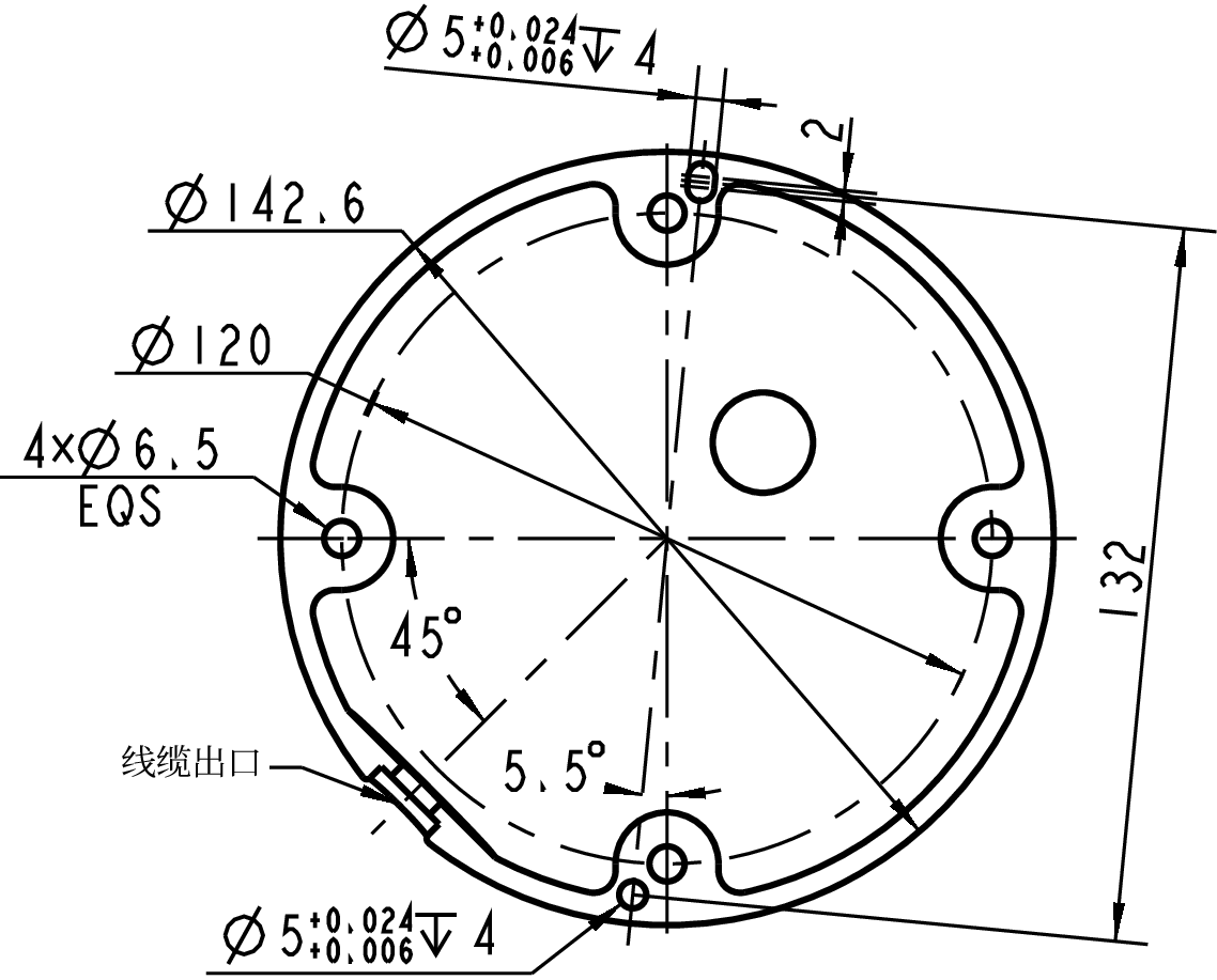
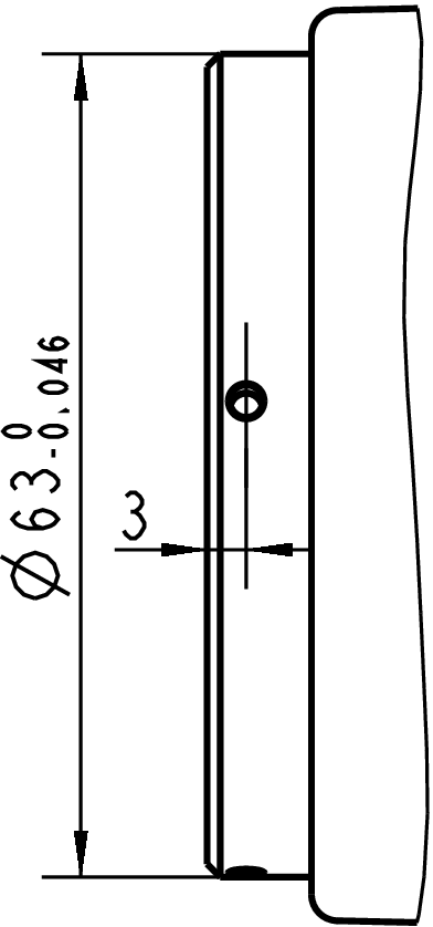
Robot Installation
The LM3 robot supports three installation methods: normal mounting, inverted mounting, and side mounting (when side-mounted, ensure the robot cable outlet is facing downwards).
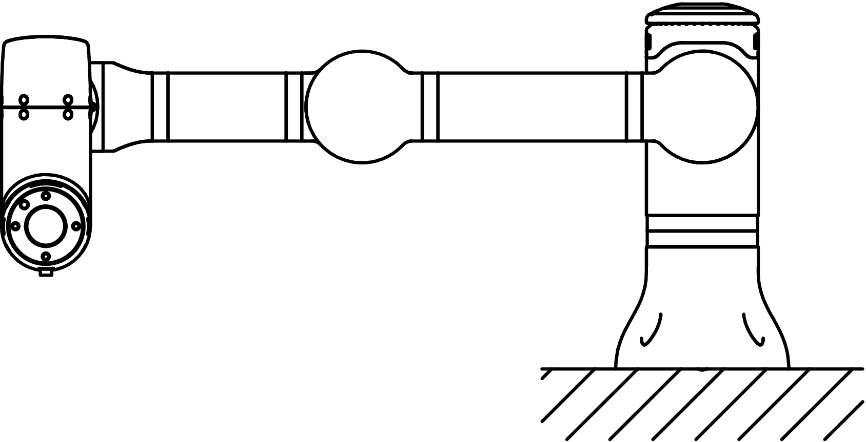
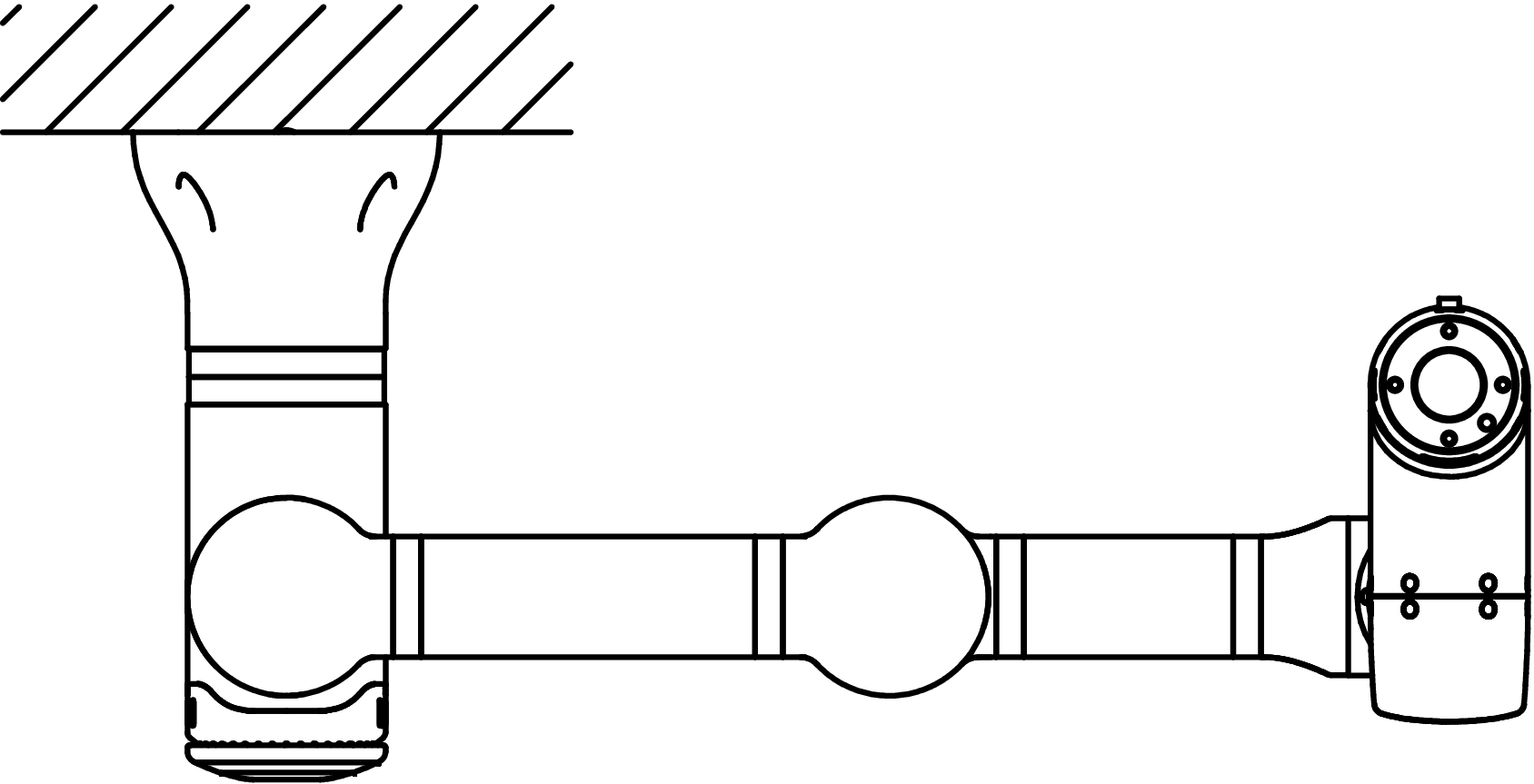
Use the 4 M6 screws in the robot accessory package to perform the installation operation corresponding to the 4 mounting holes on the robot base shown in the figure below. It is recommended to tighten these screws with a torque of 9 N·m.
If you need to adjust the robot position more accurately, you can also drill 2 holes with a diameter of 5 mm and fix them with pins.
WARNING
- Screws should be fixed in each mounting hole of the robot.
- When installing the robot, hold the robot until all screws on the base are fully tightened.
Warning
Do not fix the robot (including the control box) in an unstable position, otherwise it may fall and be damaged.
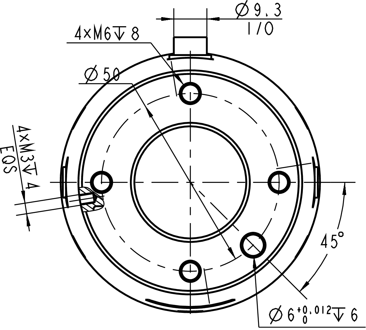
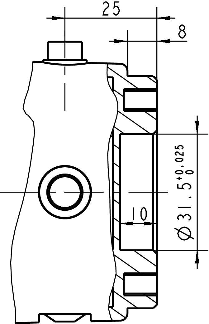
End Tool Installation
As shown in the figure below, the front of the robot's end flange plate has 4 M6 threaded holes for connecting end tools to the robot; the side of the flange plate has 4 M3 threaded holes for installing LeBai lightweight end tools. Under normal use and excluding external collision situations, the robot end (including tools) can withstand a maximum load of 3 kg.
Effective Payload
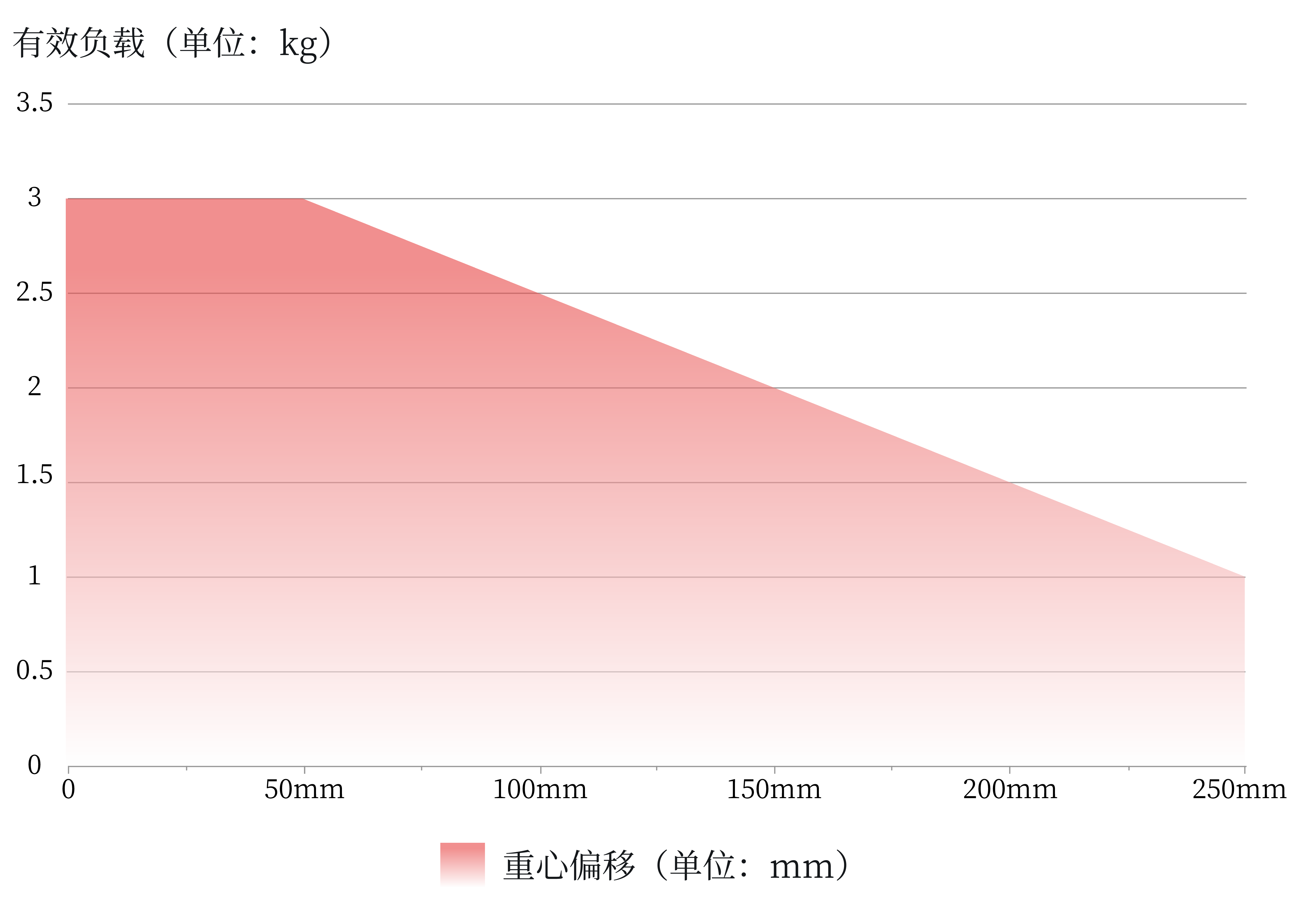
The maximum allowable effective payload of the robot depends on the center of gravity offset, as shown in the above figure. The center of gravity offset is defined as the distance along the normal direction of the flange end face between the center of the tool output flange end face and the center of gravity.
Warning
- Load conditions should be within the range shown in the chart.
- The effective payload shown in the figure represents the maximum load capacity, and under no circumstances should the maximum weight shown in the figure be exceeded.
- Exceeding the allowable value will lead to premature damage of internal components of the machine.
L Master is a robot control system customized by our company for robots. All visual operations and control of the robot must be performed after logging into the L Master system. ↩︎
It is recommended to use Google Chrome browser, Microsoft Edge browser, or other modern browsers based on the Webkit kernel for a better experience. ↩︎