Position and Pose
Joint Position Description
The LeBai LM3 robot is a six-axis (six-joint) robot. The rotation amount of each joint forms the joint position description (referred to as joint position), which can be represented as a six-tuple:
Where represents the rotation angle of the i-th joint, in radians (rad).
In Lua API, it is represented by an associative array with specified index keys.
In Lua SDK, it is represented by an array with numeric sequential indices.
For example, for the joint position
In Lua API, it can be represented as:
{j1=0.024, j2=math.rad(-15), j3=math.pi, j4=math.pi/2, j5=math.rad(30), j6=0}
In Lua SDK, it can be represented as:
{0.024, math.rad(-15), math.pi, math.pi/2, math.rad(30), 0}
The range of joint description is theoretically unlimited, with specific limitations depending on the particular application scenario and potential self-interference.
Cartesian Space Pose Description
The Cartesian position and orientation of the LeBai robot end-effector (referred to as spatial position or pose) is represented as a six-tuple:
Where represents the spatial Cartesian coordinate position in meters (m). represents the rotational pose in radians (rad).
In Lua API, it is represented by an array with numeric sequential indices.
In Lua SDK, it is represented by an associative array with specified index keys.
For example, for the cartesian space pose
In Lua API, it can be represented as:
{0.2, 0, 0, math.pi/2, math.rad(30), 0.024}
In Lua SDK, it can be represented as:
{x=0.2, y=0, z=0, rz=math.pi/2, ry=math.rad(30), rx=0.024}
For describing coordinate system (pose) , we use the following descriptions:
- X-Y-Z fixed angle. First, align coordinate system with the known reference coordinate system . Then rotate around by angle , then around by angle , and finally around by angle .
- Z-Y-X Euler angles. First, align coordinate system with the known reference coordinate system . Then rotate around by angle , then around by angle , and finally around by angle .
- RPY rotation angles. X-Y-Z fixed angles can also be defined as RPY rotation angles, i.e., Roll angle , Pitch angle , and Yaw angle . First, align coordinate system with the known reference coordinate system . Then rotate around by the roll angle, then around by the pitch angle, and finally around by the yaw angle.
The rotational pose of LeBai robots is described using Z-Y-X Euler angles. Their relationship is as follows:
When developers need to convert between LeBai's pose and other pose representations, transformation through selection matrices is required. RPY or quaternions are commonly used to describe orientation in computer programming. Here's the formula for converting RPY to matrix:
Here's the formula for converting a 3×3 rotation matrix to RPY:
Specifically, when , . In this case, take , and .
Here's the conversion implementation in KDL (C++):
Rotation Rotation::EulerZYX(double Alfa,double Beta,double Gamma) {
    return RPY(Gamma,Beta,Alfa);
}

void Rotation::GetEulerZYX(double& Alfa,double& Beta,double& Gamma) const {
    GetRPY(Gamma,Beta,Alfa);
}

Rotation Rotation::RPY(double roll,double pitch,double yaw) {
    double ca1,cb1,cc1,sa1,sb1,sc1;
    ca1 = cos(yaw); sa1 = sin(yaw);
    cb1 = cos(pitch);sb1 = sin(pitch);
    cc1 = cos(roll);sc1 = sin(roll);
    return Rotation(ca1*cb1,ca1*sb1*sc1 - sa1*cc1,ca1*sb1*cc1 + sa1*sc1,
                    sa1*cb1,sa1*sb1*sc1 + ca1*cc1,sa1*sb1*cc1 - ca1*sc1,
                    -sb1,cb1*sc1,cb1*cc1);
}

// Gives back a rotation matrix specified with RPY convention
void Rotation::GetRPY(double& roll,double& pitch,double& yaw) const {
    double epsilon=1E-12;
    pitch = atan2(-data[6], sqrt( sqr(data[0]) +sqr(data[3]) )  );
    if ( fabs(pitch) > (PI_2-epsilon) ) {
        yaw = atan2(  -data[1], data[4]);
        roll  = 0.0 ;
    } else {
        roll  = atan2(data[7], data[8]);
        yaw   = atan2(data[3], data[0]);
    }
}
Robot Kinematics
For robot motion, when joint positions are specified, theoretically any position can be reached as long as self-interference (i.e., hitting itself) does not occur. When a set of joint positions is determined, and the TCP settings are determined, the robot's pose is also determined and unique. This calculation process is the robot's forward kinematics.
When specifying spatial positions, the situation becomes quite different. Due to the robot's configuration, the inverse kinematics of converting spatial positions to joint positions has multiple solutions or no solution. The robot cannot reach any arbitrary point in space, which is a physical limitation. The robot also cannot perform arbitrary motion between two points in space—this phenomenon is particularly evident when the robot is in a "singular position", where executing spatial movement commands is likely to cause algorithm failure, forcing the robot to stop moving.
When the following error messages appear during robot motion, please modify the movement commands in the scene or program, and use teaching or joint movement to restore the robot to a normal position.
D-H Parameters
LeBai robots use modified D-H parameters for kinematic description of the robot.
| Joint | (unit: m) | (unit: m) | (unit: rad) | |
|---|---|---|---|---|
| 1 | 0 | 0.21583 | 0 | 0 |
| 2 | 0 | 0 | 0 | 1.5708 |
| 3 | 0 | 0 | -0.28 | 0 |
| 4 | 0 | 0.12063 | -0.26 | 0 |
| 5 | 0 | 0.09833 | 0 | 1.5708 |
| 6 | 0 | 0.08343 | 0 | -1.5708 |
Due to manufacturing and assembly errors, there will always be some deviation between the actual DH parameters of each robot and the theoretical values. LeBai performs precise calibration of the actual DH parameters before each robot leaves the factory. Customers who need to perform visual grasping, offline simulation, and other applications can consult with developers for detailed information.
Singular Positions
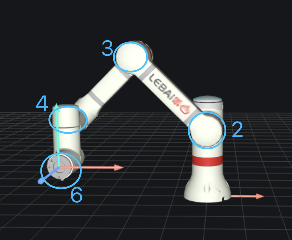
There are three typical singular positions:
- Four axes parallel, i.e., the 2nd, 3rd, 4th, and 6th joints are in a parallel state.
- Zero position, i.e., when all joint angles of the robot are 0.
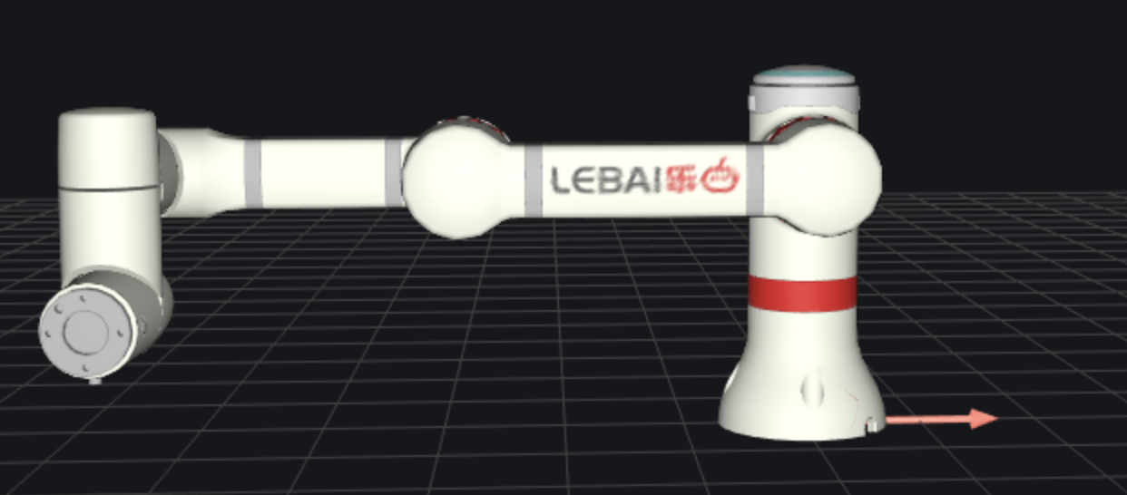
- When the robot arm is fully extended in any position